Sir jim l . . . . .
I think that a small dynamic testing of the circuitry components might be in order, to confirm functionality of its composite parts an then go backwards to see just what is failing / failed in the state that you have the unit now.
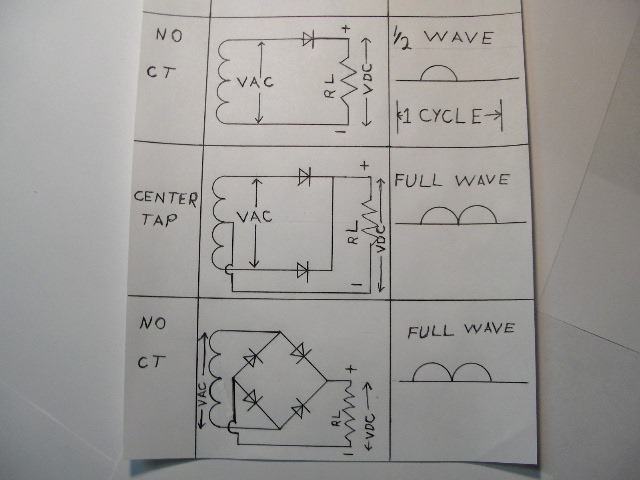
Here are the circuit possibilities . . . now with you not having a CT on the transformer the mid circuit is eliminated and with you having TWO selenium rectifiers, the top circuit is eliminated, therefore the bottom FWB circuitry must be your applicable circuit.
Those may just be large single plate selenium rectifiers and mechanicaly mounted to the charger case for more effective thermal out transfer of developed heat.
I'm starting by assuming that the units have adequate symbolization left on the units to positively determine the + and - polarities of the units sections.
Now, if my unit to be evaluating I would get 4 of the 1N4001 /on up thru/ 1N4007 silicaon rectifier diodes and jumper clip lead 1 each of them across the individual selenium rectifier sections.
That should result in a reduced power supply capability of ~ 2 amps and then you could dump the output into a 5 ohm load resistor . . .if this is a 6V charger . . .or a 10 ohm load resistor . . . (if this is a 12 V charger ???) and then just feel the warm heating up resistor.
Or you could use an incandescent bulb as a VISIBLE test lamp, if being of the proper voltage and not pulling more than that 2 A of available current from the diode set.
If using the resistor load, just feeling the resistor heat should confirm its loading action, if metering the output, shunting in ~20 ufds of filtering across the load resistor should help your DC metering . . . as compared to the way your meter responds to otherwise having , raw pulsating DC input.
If the unit checks out with the subbed in silicon diodes at a reduced capability, looks one need to investicgate the selenium rectifiers. If you have one lead of a selenium unit disconnected, you should be able to initiate the conventional forward / backwards resistance testings of an ohmmeter being connected across a unit.
BUT on them, DO expect a higher forward resistance and the presence of SOME back resistance in the reverse test mode.
I'm blind and therefore can't see the individual selenium rectifier plates construction as well as the number and size of plates.
But one basically can expect the bulk of a single plates construction to be an alumuni-ninny-yum-yum plate with a layer of selenium all over one plate side and its top side center having a compressed connection made in the center with a terminal washer in the order of this:

The back side of the aluminum plate has a like connection.
As for any FIBER / plastic washers I have seen being utilized . . . be they round or square configurations . . . they were associated with covering up that connection made to that mentioned top "hot" side terminal lugs central connection.
Additionally there is usually a central hollow insulating spacer which runs thru the unit, thus providing for the insulation from a mounting bolt run thru the unit.
Now, if the unit is working in low power testing configuration, suspect the seleniums.
73's de Edd

