It has a 6x4 rectifier and a 6AU6 with PP 6AQ5s.
I have two of these little amps to try to combine for stereo.
One arrived with a cooked transformer ( need a new one) and this one's transformer was running rather hot as well.
I was also missing one 6X4 tube anyway so I thought I'd try to combine two solutions into one.
First was to cool off that transformer and the 2nd was to replace the 6X4.
I saw that the 6x4 draws 600 ma so just eliminating that alone will give the transformer a lot of breathing room to cool off.
I also did not want to modify the circuit, in case I ever wanted to pop another 6X4 back in there.
So I decided to make a simple SS full-wave rectifier using two 1n4007 diodes... but I'd also have to drop the B+
What with higher line voltage nowadays and all...I needed NOW to drop about 65 Volts DC.
The B+ load draws 50ma so that would have meant I'd need a 1300 ohm resistor at about 5 watts at least
I didn't have that large of a resistor so I split it up into two 680 ohm resistors and put them on the AC side of the diodes. I still needed at least 2 or 3 watt resistors and I only had some 1 watt-ers around here...(in metal film at least).
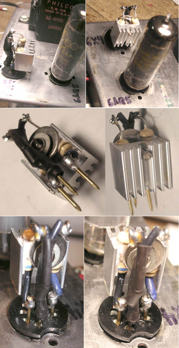
So since I also have a glut of heat-sinks laying around the joint, I decided to make an all-in one 6X4 replacement that would plug right into the socket with a pair of 680 ohm resistors mounted on a heat-sink and combined with the two diodes as a single little 1-piece unit.
I soldered three little brass brads on the leads to act as "tube-pins" and they seem to fit perfectly snug into the socket.
It works fine and BOY did that transformer cool right down big time!
Take a look. In the schematic I showed you right where the brass nails are soldered on: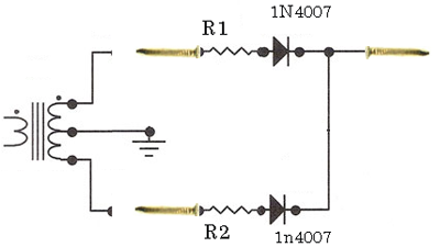
Nice module. Something Bill Turner might like to add to his internet site.
Want to comment about your resistors. If you would need 1 - 1300 ohm resistor then you would need 2600 ohms on each side but there is more to figure.
With waveform of a rectfier current will be a lot higher but for shorter period of time.
I am sure you measured voltage and 680 ohms gave what you needed. They will dissipate more than calculated.
Norm
:I've been restoring this little Philco audio amp that I found on Ebay.
:It has a 6x4 rectifier and a 6AU6 with PP 6AQ5s.
:
:I have two of these little amps to try to combine for stereo.
:
:One arrived with a cooked transformer ( need a new one) and this one's transformer was running rather hot as well.
:
:I was also missing one 6X4 tube anyway so I thought I'd try to combine two solutions into one.
:
:First was to cool off that transformer and the 2nd was to replace the 6X4.
:I saw that the 6x4 draws 600 ma so just eliminating that alone will give the transformer a lot of breathing room to cool off.
:
:I also did not want to modify the circuit, in case I ever wanted to pop another 6X4 back in there.
:So I decided to make a simple SS full-wave rectifier using two 1n4007 diodes... but I'd also have to drop the B+
:
:What with higher line voltage nowadays and all...I needed NOW to drop about 65 Volts DC.
:The B+ load draws 50ma so that would have meant I'd need a 1300 ohm resistor at about 5 watts at least
:
:I didn't have that large of a resistor so I split it up into two 680 ohm resistors and put them on the AC side of the diodes. I still needed at least 2 or 3 watt resistors and I only had some 1 watt-ers around here...(in metal film at least).
:
:So since I also have a glut of heat-sinks laying around the joint, I decided to make an all-in one 6X4 replacement that would plug right into the socket with a pair of 680 ohm resistors mounted on a heat-sink and combined with the two diodes as a single little 1-piece unit.
:
:I soldered three little brass brads on the leads to act as "tube-pins" and they seem to fit perfectly snug into the socket.
:
:It works fine and BOY did that transformer cool right down big time!
:Take a look. In the schematic I showed you right where the brass nails are soldered on:
:
:
:
Yes! You're so right...
I did measure the B+ now at 250v now as needed but trying to calculate those resistors was not really logical.
And partly, I guess, because the pulsating DC after the regulator is not able to be read quite properly by the DC volt meter...
And on the AC side each resistor is only seeing part time (1/2 cycle) duty.. right?
So yeah it was a bit confusing.. lol
...and I got lucky to get the correct +250v DC B+ with only a little tweaking.
Is there really an accurate way to calculate and do this easily?
No easy way to calculate these resistors. Too many variables. It would depend on load and input filter cap value. What a wave form.
It would be nice if we could just call it half cycle but charging time is less than that. A diode charges the filter cap. Depending on how much voltage drops during a cycle determines charging time. The diode will only charge when the cycle is above voltage on the cap. With a very large cap it might only be 10% of a cycle? The diode has to charge this cap during this fraction of a cycle. If it's only 10% and we need 50 ma that would be 500 ma during charging.
That's why we see surge current specified. 1N4004 is a 1 amp diode but surge is 30 amps.
http://www.datasheetcatalog.org/datasheet/vishay/1n4001.pdf
Norm
:Hi Norm:
:Yes! You're so right...
:I did measure the B+ now at 250v now as needed but trying to calculate those resistors was not really logical.
:And partly, I guess, because the pulsating DC after the regulator is not able to be read quite properly by the DC volt meter...
:And on the AC side each resistor is only seeing part time (1/2 cycle) duty.. right?
:So yeah it was a bit confusing.. lol
:...and I got lucky to get the correct +250v DC B+ with only a little tweaking.
:
:Is there really an accurate way to calculate and do this easily?
:
But this time around, they are making the trip , and being visible. 73's de Edd
|


:
:Hi Peter
:
: No easy way to calculate these resistors. Too many variables. It would depend on load and input filter cap value. What a wave form.
:
: It would be nice if we could just call it half cycle but charging time is less than that. A diode charges the filter cap. Depending on how much voltage drops during a cycle determines charging time. The diode will only charge when the cycle is above voltage on the cap. With a very large cap it might only be 10% of a cycle? The diode has to charge this cap during this fraction of a cycle. If it's only 10% and we need 50 ma that would be 500 ma during charging.
:
: That's why we see surge current specified. 1N4004 is a 1 amp diode but surge is 30 amps.
:
:http://www.datasheetcatalog.org/datasheet/vishay/1n4001.pdf
:
:Norm
::Hi Norm:
::Yes! You're so right...
::I did measure the B+ now at 250v now as needed but trying to calculate those resistors was not really logical.
::And partly, I guess, because the pulsating DC after the regulator is not able to be read quite properly by the DC volt meter...
::And on the AC side each resistor is only seeing part time (1/2 cycle) duty.. right?
::So yeah it was a bit confusing.. lol
::...and I got lucky to get the correct +250v DC B+ with only a little tweaking.
::
::Is there really an accurate way to calculate and do this easily?
::
:
:
Good Idea!
I'll try to find a fiber or such heat-resistant non-conductive material as a replacement before the "smoke" shows up...lol
Now that I think about it I think I still have a 6" wide roll of thick white Teflon. Might even still have some beryllium oxide washers around from the late 60s.
Just for you... I now have a nice doubled-over thick Teflon sheet with a hole punched in the center working perfectly as a washer
... AND protecting them-there resistors.
Thanks for the sensible suggestion.
Yeah, now that I think about those finer points... it is a weird thing to try to calculate for. Especially the threshold of diode conduction based on the charge level voltage of the caps.
Never thought too deeply about that .. but boy you are right!!