New here, so please bear with me. I have just acquired a Zenith 5S-218 that restoration had been started on. Some wires were left unattached under the chassis. I am so-so at following a schematic, so I am having trouble figuring things out. The electrolytic can has been replaced with separate caps but the plus sides were left unattached? Also it seems that some wires going to the antenna and oscillator coils are not attached. I am having trouble figuring out which lugs on the coils to use as they don't seem to be marked. If anyone has a good picture of the wiring it would help greatly! It is also missing the 2 "sled" feet. I can reproduce these as I work in a millshop. I just need to know the correct dimensions. (length, width, thickness). Sorry for the long post, but I am stumped for the time being! Thanks for any help and best regards,
Tim
Cubo-cubo . . . . Here ya' goes on those electrolytics, with contrasty white, and one green sphagetti being used on the leads, they tend to show up a bit better.
|
:Hi all,
:New here, so please bear with me. I have just acquired a Zenith 5S-218 that restoration had been started on. Some wires were left unattached under the chassis. I am so-so at following a schematic, so I am having trouble figuring things out. The electrolytic can has been replaced with separate caps but the plus sides were left unattached? Also it seems that some wires going to the antenna and oscillator coils are not attached. I am having trouble figuring out which lugs on the coils to use as they don't seem to be marked. If anyone has a good picture of the wiring it would help greatly! It is also missing the 2 "sled" feet. I can reproduce these as I work in a millshop. I just need to know the correct dimensions. (length, width, thickness). Sorry for the long post, but I am stumped for the time being! Thanks for any help and best regards,
:Tim
:
:
: : : :  : : : : : : : :Sir Tim . . . . . : : : :Cubo-cubo . . . . : : : :Here ya' goes on those electrolytics, with contrasty white, and one green sphagetti being used on the leads, they tend to show up a bit better. : : :Looks like pins on the speak-ling plug are receiving the electrolytic caps positives-es-es . : : :So jab an ohmmeter lead into the filament wiring of the 5Y4 and the other end is used to probe the pins of the speaker plug, the one reading the closest to a couple of ohms is your connection point for the + lead of C15. : : :Now in the process of the probings of all of those pins you also should have come up with a reading of ~1250 ohms . : : :That is the pin the the other C16 electrolytic gets its positive connected. Confirm it for sure by reading from that connection to the screen grid of the 6F6 which is also one of several sharing the same connection nodes. : : : : :Now for the negative-bothus connections . . . . with there being one cap (C15) going to the end of the power resistor strip and the other cap (C16) going to the pin of a tube below it( the cathode of the 6F6 AF output tube). : : :That's where cross referencing to the schematic comes into play. : : :In getting to the ossifrier coil next . . . . .were any connections left intact on it ? : : : : : : 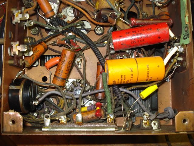 : : :73's de Edd : : : : :On the other hand . . . you have different fingers. : : : :  : |
:
:
:
:
:
:
::Hi all,
::New here, so please bear with me. I have just acquired a Zenith 5S-218 that restoration had been started on. Some wires were left unattached under the chassis. I am so-so at following a schematic, so I am having trouble figuring things out. The electrolytic can has been replaced with separate caps but the plus sides were left unattached? Also it seems that some wires going to the antenna and oscillator coils are not attached. I am having trouble figuring out which lugs on the coils to use as they don't seem to be marked. If anyone has a good picture of the wiring it would help greatly! It is also missing the 2 "sled" feet. I can reproduce these as I work in a millshop. I just need to know the correct dimensions. (length, width, thickness). Sorry for the long post, but I am stumped for the time being! Thanks for any help and best regards,
::Tim
::
:
:
Thanks a heap Edd! Only I just figured out what a huge mistake I made in posting! I have three radios I am currently working on. The "Cube" is going well. It is a Crosley 62-TD that I am having the trouble with. Must have gotten the antenna between my ears crosswired when I posted! Anyhow I have saved your info and pic of the 218 and will use it for reference! By chance do you have any such info on the 62-TD? Otherwise I will repost. Sorry about the mistake!
Regards, Tim