perhaps it would have value as a separate subject on Bucking Transformer alternatives. perfect this idea.
I also would love feed back and to see experimentation from anyone else to improve or help
In the interest of trying to find a simple and cheap, easy way to drop the normal 125v input AC down to something closer to
105VAC or so for use feeding the old power transformers. (instead of a bucking transformer)
... I decided to play "Edison" tonight and see what I could "blow-up"...lol
So I thought about making a capacitor voltage divider in front of .. or prior to the transformer .
Now... you might be thinking:
What's the advantage of two caps in a divider vs. one series cap "dropper?" Seems like extra cost and space needed?
The problem is that a capacitor in series with (an inductor) such as the transformer will oscillate like crazy. So another method
was in order.
So I tried out a bread-board circuit with a few trial components and it all SEEMS to have worked great... so far..... lol
I used a 115/10vAC door-bell-transformer and connected the 2ndary to two #47 lamps in series at the 2ndary load. ( should
be 150ma load)
When I feed a NORMAL 125VAC into the primary I get about 15vAC out on the secondary across the 2 lamps in series...
OKAY fine.
Then I made a Capacitor voltage divider by connecting an 8.2uf AC cap in series with a 2.5uf AC cap.
This seems like about an 80:20 ratio.... right? (I don't know if my thinking is clear on that logic)
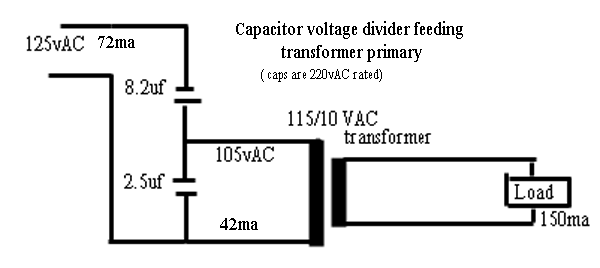
Anyway .... I went on to feed 125 VAC across the entire divider.
Then I connected the transformer across only the 2.5uf (shunt) cap to feed the primary.
The 125vAC feed drops down to 105vAC across the 2.5uf cap... thereby loosing 20vAC with no heat loss!!
Feeding the transformer with 105vAC now ... it dropped the secondary output down to 12vAc... fine!
The total current feeding the whole divider is about 72ma and the current feeding the transformer primary from across the
2.5uf cap is 42ma
Seems like a good idea... no? ... Or am I just simply "lucky" that the primary does not oscillate with the 2.5uf cap?
My example is using relatively low current loads... so I'm not exactly sure that if a much larger load would require much larger
value caps.
... and if so, it may not be practical to buy the much larger-sized AC caps compared to the cost of a bucking
transformer.
Note update:
To drop the 125volts down to only 112vAC instead of 105VAC ....I decided to change the cap values to 8uf and 1uf to
achieve a result closer to 112vAC.
That worked perfectly.
Then with 112VAC feeding the transformer I decided to increase the secondary load considerably to see if these particular
values could be used to drive a heavier load.
So I increased the load on the secondary of the transformer to approximately 600ma
(using 3 paralleled sets of two #51 bulbs in series. Each 2-bulb series-set draws 200ma)
At this point the load was drawing 600ma and the primary was drawing only about 110ma.
Here's a note I just found on simple capacitor voltage divider theory:
.. (I've shown approximately the same example values as in my circuit pictured above 8uf and 2uf) capacitors, so the DC case is not relevant. The formula for determining the AC output voltage of a capacitive divider is different from the resistive and inductive dividers, because the series element, C1 is in the numerator instead of the shunt element, as shown below: Vout = Vin * C1/(C1+C2) ...... where C1= 8uf and C2=2uf 100VAC. Note that the output voltage is not dependent on the input frequency. However, if the reactance of the capacitors is not large at the frequency of interest (i.e. capacitance not large enough), the output current capability will be very low. "
"Capacitive dividers can be used with AC input signals. A DC input voltage would not pass through the
Example: In the following circuit, the output voltage would be: Vout = 125VAC * 8uF / (8uF + 2uF) =
Interesting possibilities here I guess. I'll have to fool around on the bench with it.
Thanks for the idea.
Carl