:
:Hi!
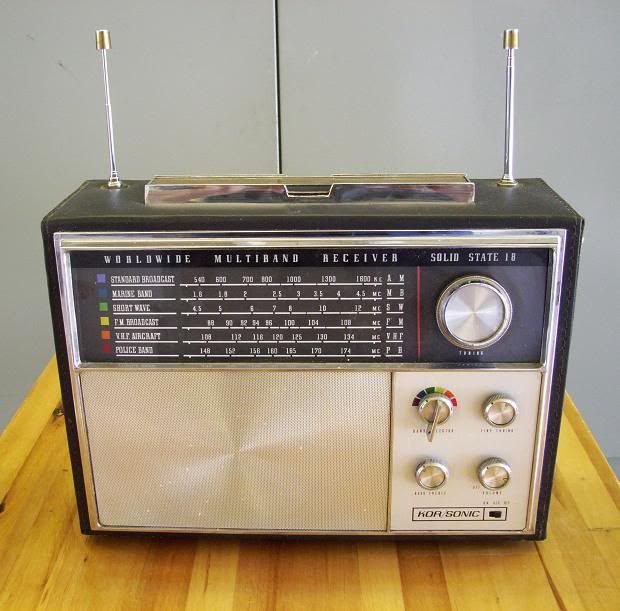
Would vanyone know where I can get a schematic for a KOR/SONIC model 1860 transistor radio? Thanks for looking.
Bob Masse
:
:
:
:
: Hi! Gary,
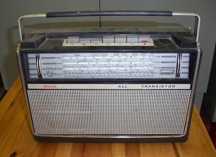
I try and stay away from transistor radios but this one is changing my opinion on that. It looks so cool with dual antennas and has a very clear sound and excellent reception. It just doesn't work on AM. I've picked up aircraft on it and excellent FM. So this one is my first keeper in the transistor line. The other one I'm hooked on is a Philips L4X26T.
Bob Masse
:
:
:
:
OK Gary,
I'm rusty at this so it may take more than one try.
Bob Masse
:
:
::
::
:OK Gary,
:I'm rusty at this so it may take more than one try.
:
:
:
:Bob Masse
::
::
:Here is the Philips radio.The chrome bar on the front actually lifts to the upright position and is the antenna.
Bob Masse
:
:
:
:
:
:
:Warren,
Thanks for the tip.
Gary,
Glad you enjoyed the photo.
Bob Masse
:
:
::
::
:OK Gary,
:I'm rusty at this so it may take more than one try.
:
:
:
:Bob Masse
Bob, thanks for making the effort to post the pic. I do remember that set. I had a lower end Kor/Sonic model that I purchased in 1970. I used it until it fell apart on me sometime in the 1980s. My set had a padded case and only SW and Marine Bands, in addition to AM and FM. Thanks for brining back the meomories and good luck getting it running properly.
Into initially taking into consideration, that sets specifications: |
:::Would you mind posting a pic? Maybe I'll remember it from my many visits to the electronics department so many years ago. ::: ::Bob Masse
:::
::OK Gary,
::I'm rusty at this so it may take more than one try.
::
::::http://i951.photobucket.com/albums/ad357/bigbob2008photos/PHILIPSL4X26T.jpg>
::
:
:Bob, thanks for making the effort to post the pic. I do remember that set. I had a lower end Kor/Sonic model that I purchased in 1970. I used it until it fell apart on me sometime in the 1980s. My set had a padded case and only SW and Marine Bands, in addition to AM and FM. Thanks for brining back the meomories and good luck getting it running properly.
:
:
: : : :  : : : : : : : :Sir Bob. . . . . : : : :Into initially taking into consideration, that sets specifications: : : :1967 vintage KOR/SONIC Model 1860 : : :AM/FM/MB/SW/VHF/PB : : :AC/DC receiver: : : :18 transistor AC/DC : : :6 band radio covering : : :AM (540-1600kc) : : :MB (1.6 – 4.5mc) : : :SW (4.5 – 12mc) : : :FM (88-108mc) : : :VHF (108-134mc) : : :PB (148-174mc) : : :One can see the only inoperative function being the AM band with there being a HIGH commonality with the shared RF circuitry of the MB amd SW bands. : : :That set shows to be using a rotary band switch, which I tend to see as being quite a bit more reliable in its contact action than the Pushbutton type of band switching used on many other foreign derivative sets. : : :I have sent out a couple of feelers for this sets schematic, but with no comebacks to date. : : :If my set to evaluate . . . I would confirm that a " selectively" dirty or contact tensioned faulted band switch in the AM mode is :probably not at fault. (At least . . .not very likely ) : : :Then I would move to the tuning condenser for the AM-MB-SW bands and its two sections involving the Mixer and Local oscillator circuits. : : :Ignore the tuning condensers two smaller vaned sections for the VHF-FM-PB . . . .that being considered, that those three bands are not covered with a common, separate tuner being, apart from the AM portion. : : :Once you have zeroed in on the TUNING CONDENSERS Mixer section (the one with the most rotor plates) and the Oscillator section ( the one with the fewer rotor plates), then place the band switch in either of the operative MB and SW bands. : : :Take an ohmmmeter and connect one lead to the frame of the tuning condenser and the other lead to the terminal associated with the MIXER section of the tuning condenser, you should then read the continuity of the mixers coil which the band switch has inserted for the operation on that selected band. :THEN you switch to the problematic AM BCB band and see if there is ALSO a like CONTINUITY of a coils presence when being placed in the AM BC band.( That's really where Sir Warrens prior mentioned BCB loop antennas presence aspect is detected. ) : : :If continuity is passed in that AM test, then we move on to do the the oscillator sections test aspect. : : :Take an ohmmmeter and connect one lead to the frame of the tuning condenser and the other lead to the terminal associated with :the OSCILLATOR section of the tuning condenser, this time you should read the continuity of the oscillator coil which the band switch has inserted for the operation on that selected (MB-SW) band. : : :THEN you switch to the AM BC band and see if there is a like CONTINUITY of an oscillator coils presence when placed in the AM BC band. : : :By doing this set of tests you should pretty well have shaken down the possibility of the problem being and / or isolated to the oscillator or mixer coil of the AM BC band portions of the receiver or else, a band switching contacts / continuity problem. : : : : : : : : :73's de Edd : : :  : |
:
:
:
:
FACE="Comic Sans MS"COLOR=800000>
:
:::
:::
:::
:
:
:
:Hi! Edd,
Thanks for the excellent info.WhenI get time next week I'll check it out.
Bob Masse
:
: