Got no schematic for this one and can't seem to locate info anywhere so this potential refurb could take some time.
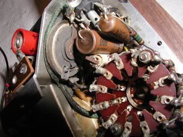
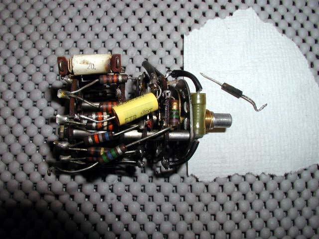
:Potential project-currently evaluating. This is a NRI VTVM / model 11, in pretty good shape. Needs the usual attention. But what is this part in photo with question mark identifier? Looks like wires wrapped in paper.
:Got no schematic for this one and can't seem to locate info anywhere so this potential refurb could take some time.
:
:
:Got no schematic for this one and can't seem to locate info anywhere so this potential refurb could take some time.
:
:
Scott,
I am looking in my files for the schematic for the VTVM. I restored one about six months ago. National Radio Institute. Edd was very helpful with the unit once we obtained the schematic from someone on the Forum. Hopefully the same poster will send you the info if i can't find it, it is out there. It was not a bad unit but not as good as the Eico and RCA VTVM's.
(12BH7 /or / 12AU7 and a 6X4 and probably a selenium rectifier also.) Thassit . . . . from all that I was initially given to wuk with . . . . . .tell us 'mo . . . .tell us 'mo . . . .tell us 'mo ! . . . . . . a . . . la . . . West Side Story. |


le SCHEMATIQUE:  |
:Scott,
::Potential project-currently evaluating. This is a NRI VTVM / model 11, in pretty good shape. Needs the usual attention. But what is this part in photo with question mark identifier? Looks like wires wrapped in paper.
::Got no schematic for this one and can't seem to locate info anywhere so this potential refurb could take some time.
::
::
:
:I am looking in my files for the schematic for the VTVM. I restored one about six months ago. National Radio Institute. Edd was very helpful with the unit once we obtained the schematic from someone on the Forum. Hopefully the same poster will send you the info if i can't find it, it is out there. It was not a bad unit but not as good as the Eico and RCA VTVM's.
:
:
Edd- in researching this prior to posting I found your previous info on the NRI/W model.
This model has a 6x4 and 12AU7(same as 12BH7 in W.)
There is a selinium rectifier. Also the electrolytic is a 10mfd/150v. The paper/wax caps are: 3- .002uf and 1 -.02uf, all 600v. Looks like W is 3-.01uf.
The model 11 has 2/C cells for the ohms part of the meter. the W has 1/1.5 cell.
Haven't really gotten into the circuit tracing yet but will in the near future.
:Thanks for the info Planigan/ hope the schematic turns up. Another meter....it is habit forming!
:Edd- in researching this prior to posting I found your previous info on the NRI/W model.
:This model has a 6x4 and 12AU7(same as 12BH7 in W.)
:There is a selinium rectifier. Also the electrolytic is a 10mfd/150v. The paper/wax caps are: 3- .002uf and 1 -.02uf, all 600v. Looks like W is 3-.01uf.
:The model 11 has 2/C cells for the ohms part of the meter. the W has 1/1.5 cell.
:Haven't really gotten into the circuit tracing yet but will in the near future.
:
Also included in the photo is a 1.5meg charred resistor and the reason I removed wafer switch. It was located between 2nd/3rd wafers and rubbing aginst switch center. It looks burnt, there is a chunk out of it, the wafer was black, but the resistor still measured 1.6meg. Unexplainable?
Still searching the schematic for NRI model 11 as resistor values don't mesh up with W model.
: Update on the mystery part. Turns out it is a wire wrapped in paper 20 ohm resistor. I wonder why this kind of resistor was used? It is the RX1/3v location.
:Also included in the photo is a 1.5meg charred resistor and the reason I removed wafer switch. It was located between 2nd/3rd wafers and rubbing aginst switch center. It looks burnt, there is a chunk out of it, the wafer was black, but the resistor still measured 1.6meg. Unexplainable?
:
:
:Still searching the schematic for NRI model 11 as resistor values don't mesh up with W model.
:
:
:
:
:: Update on the mystery part. Turns out it is a wire wrapped in paper 20 ohm resistor. I wonder why this kind of resistor was used? It is the RX1/3v location.
::Also included in the photo is a 1.5meg charred resistor and the reason I removed wafer switch. It was located between 2nd/3rd wafers and rubbing aginst switch center. It looks burnt, there is a chunk out of it, the wafer was black, but the resistor still measured 1.6meg. Unexplainable?
::
::
::Still searching the schematic for NRI model 11 as resistor values don't mesh up with W model.
::
::
:
:
I have the meter working ok on ohms and DC but AC is not working correctly. The meter wavers and sometimes stablizes.Voltage measures much lower than actual on AC. The measured voltage coming out of selenium rectifier seems low at 85v and filament voltage is low at 3.5 so I have to figure this out.

Divider resistors for a lot of these old meters were made up of screened combinations, probably using a bridge and precision standards. You can do the same with a modern DVM.
The ohms resistors should add up to the mid scale value for each range. In other words the total resistance in series with the battery should be equal to the mid scale reading for the selected range. The resistor function uses the voltage divider method, so if the unknown resistor is the same as the series resistance, the meter will read half scale, and so forth.
The voltage divider network is setup so that the ratios of resistance correspond to the ratio of each selected range to the maximum range. This is to make the maximum voltage applied to the bridge tube the same for each range. In this case the highest range is 1200 volts and the lowest is 3 volts so the the 1200 volt range requires a division of 400 to 1. Similarly the 300 volt range requires a division of 100 to one, and so forth.
You can easily figure the appropriate divider resistors if you know the overall input resistance of the VTVM. For istance, if the meter has an input resistance of 10 megs, a highest range of 1500 volts and a lowest of 1.5 volts, the divider chain must scale the input down by a factor of 1000. Therefore the lowest resistor in the chain (to lower the input to the tube the most) must be 0.001 of the total or 10k. For the 50 volt range, the input must be scale down by a factor of 0.03, giving a resistance value of 300k for the part of the chain selected for the 50 volt range.
Ten megs was not always the "standard" for VTVMs. Some used 8, some 9, some used other values.
The values you found in your unit seem to be consistent with 9 megs. This gives numbers reasonably close to the marked values of your divider resitors:
22.5K (1200), 67.5K (300), 135K (120), 675K (30), 1.35M (12), 6.75M (3).
Remember that the originals were made up from screened combinations and that you can do the same.
This is one set that gives the proper ratios. There are similar sets for 8 or 10 megs. Happy figuring.
:The resistor bridge circuit posted below. As far as values most are silver band and some gold.
:I have the meter working ok on ohms and DC but AC is not working correctly. The meter wavers and sometimes stablizes.Voltage measures much lower than actual on AC. The measured voltage coming out of selenium rectifier seems low at 85v and filament voltage is low at 3.5 so I have to figure this out.
:
: