Ohhhhhh-tayyyy . . . here is how you do it to it. Comsidering that you might be having some old pigtails of the whole unit being left or else your having to track down the socket /plugs wiring to the bandswitch and chassis wiring and RF amp's tube socket. I believe that the drawing is complete enough . . . but just ask for supplification, if not clear enough for you. Thassit . . . . . . Pee Ess . . . . this posting thread had dropped soooo far down now , that you probably did not catch it . . . chech it out, it was made up for your clock radio alignment procedure.
Sir Daniel. . . . .
ALSO the color codings used are not relevant . . . they just happen to be some that I chose to use.
I can't rely on the exactness of the band switch shown on its contact action, without instead having to play with and rotate myself and measure continuity. . . . no can do !
Soooooooo . . . . lets just go in the manner of physically locating that schematically referenced [GREEN G] First-us Grid-amus of the RF amp tube and track its wiring over to the band switch via the [SOLID GREEN Buss] and flip the band switch thru its positions.
You then confirm that connection is made with the [GREEN G Prime] wire which goes down to the C1 antenna section of the tuning condensers stator portion . . . when you are in the Broadcast MANUAL tuning position.
The only other thing to be done now is to leave one ohmmeter lead on one of the the just measured junction(s) and additionally search for the [YELLOW/BLACK] or [FUCSIA/BLACK] connections into the bandswitch and see WHICH one of them shows continuity also.
That is the connection the the square, floating, unterminated connection of the loop antenna shown, connects to.
The loops other connection is already shown as being connected into to the sets AVC buss.
REFERENCING: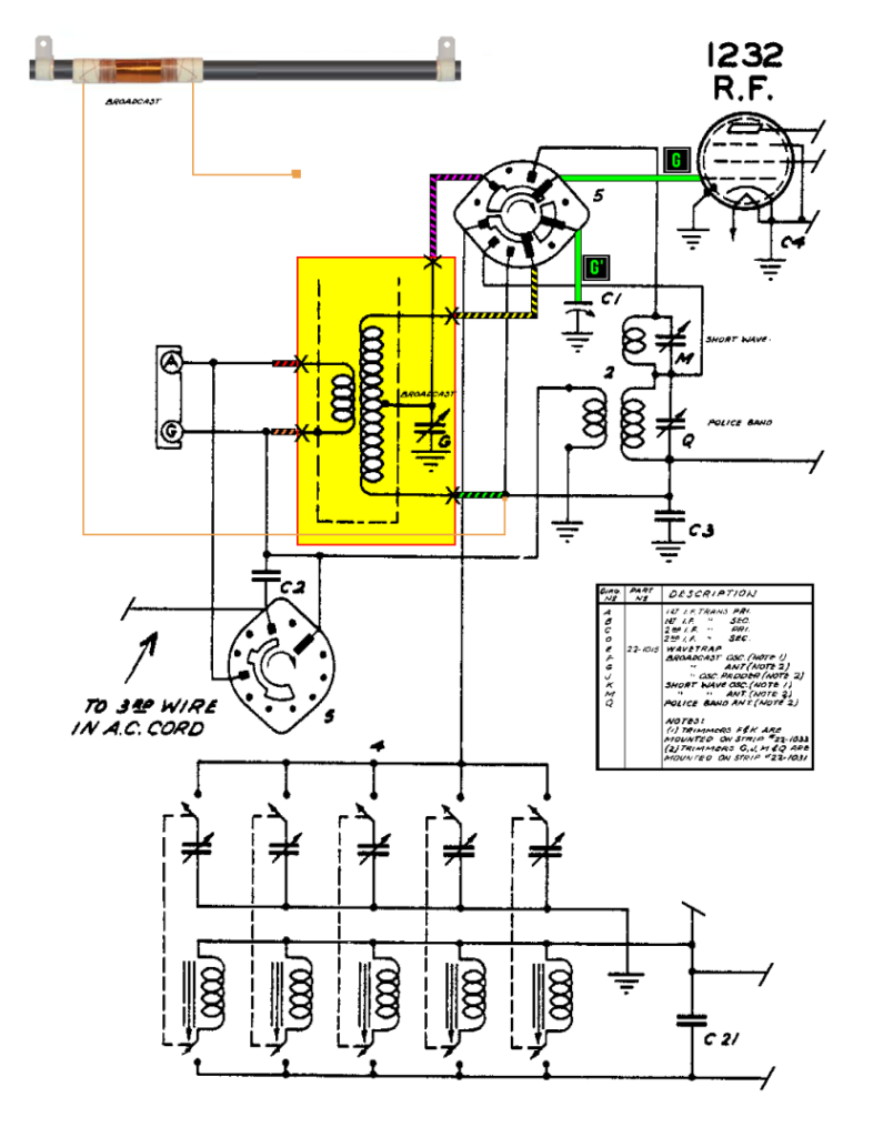
73's de Edd
:I'm working on a Zenith 7A02 chassis that I found with no Wave Magnet Antenna. Since a shortwave long wire can be connected directly to the band switch, I am wondering if I can use a Loopstick Antenna for AM reception connected to the Wave Magnet socket? Does anyone have a "pin out" diagram I can use to substitute a Loopstick?
:
No matter, I will soon obtain a single coil loopstick and put the "rascal" in the circuit just as you suggest!
--Daniel.
:
:
:
:
:
:
:
:
:
:
:
:
:
:
:
:Sir Daniel. . . . .
:
:
:
:Ohhhhhh-tayyyy . . . here is how you do it to it.
:
:
:
:Comsidering that you might be having some old pigtails of the whole unit being left or else your having to track down the socket /plugs wiring to the bandswitch and chassis wiring and RF amp's tube socket.
:
:
:ALSO the color codings used are not relevant . . . they just happen to be some that I chose to use.
:
:
:
:I believe that the drawing is complete enough . . . but just ask for supplification, if not clear enough for you.
:
:
:I can't rely on the exactness of the band switch shown on its contact action, without instead having to play with and rotate myself and measure continuity. . . . no can do !
:
:
:Soooooooo . . . . lets just go in the manner of physically locating that schematically referenced [GREEN G] First-us Grid-amus of the RF amp tube and track its wiring over to the band switch via the [SOLID GREEN Buss] and flip the band switch thru its positions.
:
:
:You then confirm that connection is made with the [GREEN G Prime] wire which goes down to the C1 antenna section of the tuning condensers stator portion . . . when you are in the Broadcast MANUAL tuning position.
:
:
:The only other thing to be done now is to leave one ohmmeter lead on one of the the just measured junction(s) and additionally search for the [YELLOW/BLACK] or [FUCSIA/BLACK] connections into the bandswitch and see WHICH one of them shows continuity also.
:That is the connection the the square, floating, unterminated connection of the loop antenna shown, connects to.
:
:
:The loops other connection is already shown as being connected into to the sets AVC buss.
:
:
:
:Thassit . . . . . .
:
:
:
:
:REFERENCING:
:
:
:
:
:
:
:
:
:
:Pee Ess . . . . this posting thread had dropped soooo far down now , that you probably did not catch it . . . chech it out, it was made up for your clock radio alignment procedure.
:
:
:
:
:
:
:
:> > > < < <
:
:
:
:
:
:
:
:
:73's de Edd
:
:
:
:
:
:
:
:
:
:
:
:
:
:
::I'm working on a Zenith 7A02 chassis that I found with no Wave Magnet Antenna. Since a shortwave long wire can be connected directly to the band switch, I am wondering if I can use a Loopstick Antenna for AM reception connected to the Wave Magnet socket? Does anyone have a "pin out" diagram I can use to substitute a Loopstick?
::
:
:
Ahhhhhhh yes . . . . . if so desired . . . one each .001 ufd isolative capacitor from antenna terminal to an overwound 1 or 2 turn link and the other end of the link grounded, should you want a coupling in of a BCB antenna signal. |
:Thanks Very Much Ed, for your very helpful illustration. Your diagram uses a two wire loopstick and I was thinking a 2 coil four wire loopstick would be necessary.
:
:No matter, I will soon obtain a single coil loopstick and put the "rascal" in the circuit just as you suggest!
:
:--Daniel.
::
::
::
::
::
::
::
::
::
::
::
::
::
::
::
::Sir Daniel. . . . .
::
::
::
::Ohhhhhh-tayyyy . . . here is how you do it to it.
::
::
::
::Comsidering that you might be having some old pigtails of the whole unit being left or else your having to track down the socket /plugs wiring to the bandswitch and chassis wiring and RF amp's tube socket.
::
::
::ALSO the color codings used are not relevant . . . they just happen to be some that I chose to use.
::
::
::
::I believe that the drawing is complete enough . . . but just ask for supplification, if not clear enough for you.
::
::
::I can't rely on the exactness of the band switch shown on its contact action, without instead having to play with and rotate myself and measure continuity. . . . no can do !
::
::
::Soooooooo . . . . lets just go in the manner of physically locating that schematically referenced [GREEN G] First-us Grid-amus of the RF amp tube and track its wiring over to the band switch via the [SOLID GREEN Buss] and flip the band switch thru its positions.
::
::
::You then confirm that connection is made with the [GREEN G Prime] wire which goes down to the C1 antenna section of the tuning condensers stator portion . . . when you are in the Broadcast MANUAL tuning position.
::
::
::The only other thing to be done now is to leave one ohmmeter lead on one of the the just measured junction(s) and additionally search for the [YELLOW/BLACK] or [FUCSIA/BLACK] connections into the bandswitch and see WHICH one of them shows continuity also.
::That is the connection the the square, floating, unterminated connection of the loop antenna shown, connects to.
::
::
::The loops other connection is already shown as being connected into to the sets AVC buss.
::
::
::
::Thassit . . . . . .
::
::
::
::
::REFERENCING:
::
::
::
::
::
::
::
::
::
::Pee Ess . . . . this posting thread had dropped soooo far down now , that you probably did not catch it . . . chech it out, it was made up for your clock radio alignment procedure.
::
::
::
::
::
::
::
::> > > < < <
::
::
::
::
::
::
::
::
::73's de Edd
::
::
::
::
::
::
::
::
::
::
::
::
::
::
:::I'm working on a Zenith 7A02 chassis that I found with no Wave Magnet Antenna. Since a shortwave long wire can be connected directly to the band switch, I am wondering if I can use a Loopstick Antenna for AM reception connected to the Wave Magnet socket? Does anyone have a "pin out" diagram I can use to substitute a Loopstick?
:::
::
::
:
: