I am working toward restoration on this radio. It does tune in a few AM and FM stations. The under chassis is very dense with paper caps. I have replaced 8 paper caps around the electrolytic can type cap to clear the way to replace it. The E cap is mounted on top of the chassis with a riveted attachment plate. There is no room to mount my new three seperate E caps under the chassis.
I need advice on removing the old cal without any damage to the circuits. Is the only solution to drill out the rivets, how best to proceed?
Welcome all ideas.
Mitch
Here is a site that has quite a few ideas on rebuloding cans.
http://www.boatanchors.org/filtercap.htm
These are a tough situation. Generally prefer to leave the cap can in situ and use a hacksaw blade to cut the can in half about 1/2" from base. Assumes hacksaw access is possible. Use a large wood screw to grip the innards to remove. Drill tiny holes by the terminals going through phenolic base in order to allow passage of axial caps leads to make connection underneath. Will need to drill an additional hole in the phenolic base for the B- connection. Wrap the negative leads of the new caps together and add a wire to lead below to make the B- connection. Use tape to put the can back to together. This avoids disturbing the wiring underneath and no flying leads. Limited to 2 caps inside the can in most instances. Richard
Anyway, unless the radio hums or the power supply seems overloaded, the e-cap doesn't need replacement.
Lack of stations is due to leaky paper capacitors, weak tubes, drifted resistors, or oxidized silver mica capacitors in the IF transformers. Since this radio uses slug-tuned IF transformers, they likely contain silver mica capacitors. Replace all of the other mentioned components, if faulty, first, and note performance. If performance doesn't improve, consider re-aligning the IF transformers. If they are badly out of alignment, and/or if you have a hard time peaking the transformers, then they likely contain oxidized silver mica capacitors. Another symptom is sensitivity that changes when you rock the IF transformers. Oxidized silver mica capacitors drop in capacity, and make poor connection to their respective spring contacts.
Also, on a side note, though you can simply replace all paper capacitors, the only critical ones are those in high-voltage/high-impedance circuits. Paper capacitors that are across, say, a cathode bias resistor, are not likely to fail, and won't affect the circuit any if the typical leakage in the millions of ohms is present.
T.
:Anyway, unless the radio hums or the power supply seems overloaded, the e-cap doesn't need replacement.
:
:T.
:
:
I don't want to sound like I'm contradicting Thomas..about "NEEDING" to replace old electrolytic caps...
Yes it may be true that you don't NEED to
... but common sense dictates that any radio that had it's electrolytic caps made back in 1951-52 ought to have them replaced now with newer technology E-caps.
Yes..it "might" still be working... but how long??
.. WHY ever take a chance when it is extremely likely that the cap is already leaking and if not soon may be??!
So for my money... No matter what the current performance is.. for the few cents and a little time now.. I'd replace those old electrolytics with new ones rather then ever have to face the possibility of having to re-open the chassis EVER again because it wasn't done properly now.
Especially if you are repairing it for a customer or a future user.
Thomas may be looking at it as though it were his radio only and might not care if it fails and he has the time to fiddle with it later.
But that's not the safest way to look at repairs.
You may give it to someone or sell it .. and then be embarrassed when it fails later.
:
::Anyway, unless the radio hums or the power supply seems overloaded, the e-cap doesn't need replacement.
::
::T.
::
::
:I don't want to sound like I'm contradicting Thomas..about "NEEDING" to replace old electrolytic caps...
:Yes it may be true that you don't NEED to
:... but common sense dictates that any radio that had it's electrolytic caps made back in 1951-52 ought to have them replaced now with newer technology E-caps.
:Yes..it "might" still be working... but how long??
:
:.. WHY ever take a chance when it is extremely likely that the cap is already leaking and if not soon may be??!
:
:So for my money... No matter what the current performance is.. for the few cents and a little time now.. I'd replace those old electrolytics with new ones rather then ever have to face the possibility of having to re-open the chassis EVER again because it wasn't done properly now.
:Especially if you are repairing it for a customer or a future user.
:Thomas may be looking at it as though it were his radio only and might not care if it fails and he has the time to fiddle with it later.
:But that's not the safest way to look at repairs.
:You may give it to someone or sell it .. and then be embarrassed when it fails later.
:
:
As far as i'am concerned no one contradicts anyone on this forum, i need all the advice i can get from you vet's. I am changing all of the waxed paper caps because i don't trust them and don't have a suitable tester to test them. The E caps i change because i know they are leaking or will in the future for my own sanity. I document the caps that i change via the schematic and test the radio with each change to monitor performance of the radio's selectivity and sensitivity. I have more paper caps to change as well as the E'e.
I WILL need help in the alignment of this radio. I have not seen the setup of this procedure before. I have a signal generator both rf and af but have not had to use it in the past.
You guys are great, i will post for more assistance as i get to the trouble i'am sure i will get into with the alignment.
Terry - NO 100 FOOT WAVE ANTENNA!!!!
Thanks to all for now
Mitch
If the radio is an AC/DC radio, where voltages are low, it is much more likely that the electrolytics will dry up and cause hum than short out and cause damage, IF they do dry up.
Peter must remember that he sent me a newer model LCD to repair in which most of the electrolytics had shorted, so don't have the idea that newer electrolytics are going to out-perform all older ones.
T.
If I am finding the use of a riveted mount plate I will dimple center punch its exact center and then use incrementally increased sizes of drill sizes and usually at about the 1/8in or so sizing . . . then the two rivet halves just fallout. These pics show how I build up an old electrolytic's casing: I go up about 1/2 of an inch from the bottom of the capacitor and either saw cut--Dremel tool cut—use tubing cutter—going completely around the capacitor can. Considered that the epoxy has now fully cured to its hardened state, the bottom left depiction shows how I drill just beside the inside terminals and pass all the way thru to come out as is shown on the upper photo. |
:If a good make American radio from the 1950s or newer has electrolytics that are performing well now, they will likely continue to perform well as long as you use the radio. Some smaller older Japanese electrolytics tend to leak due to inferior rubber seals, but most of that was rectified by the early 1970s.
:
:If the radio is an AC/DC radio, where voltages are low, it is much more likely that the electrolytics will dry up and cause hum than short out and cause damage, IF they do dry up.
:
:Peter must remember that he sent me a newer model LCD to repair in which most of the electrolytics had shorted, so don't have the idea that newer electrolytics are going to out-perform all older ones.
:
:T.
:
:
: : : : :  : : : : : : : : : :Sir Mitch. . . . . et al . . . : : : :If I am finding the use of a riveted mount plate I will dimple center punch its exact center and then use incrementally increased sizes of drill sizes and usually at about the 1/8in or so sizing . . . then the two rivet halves just fallout. : : :If there is adequate working area thereabout, a cut off wheel in a Dremel tool, in taking off minute layers of a rivet head, gets you there also. : : :A pop rivet is my preferred replacement . . . insertion tool space . . . permitting. : : : :These pics show how I build up an old electrolytic's casing: : : : : : 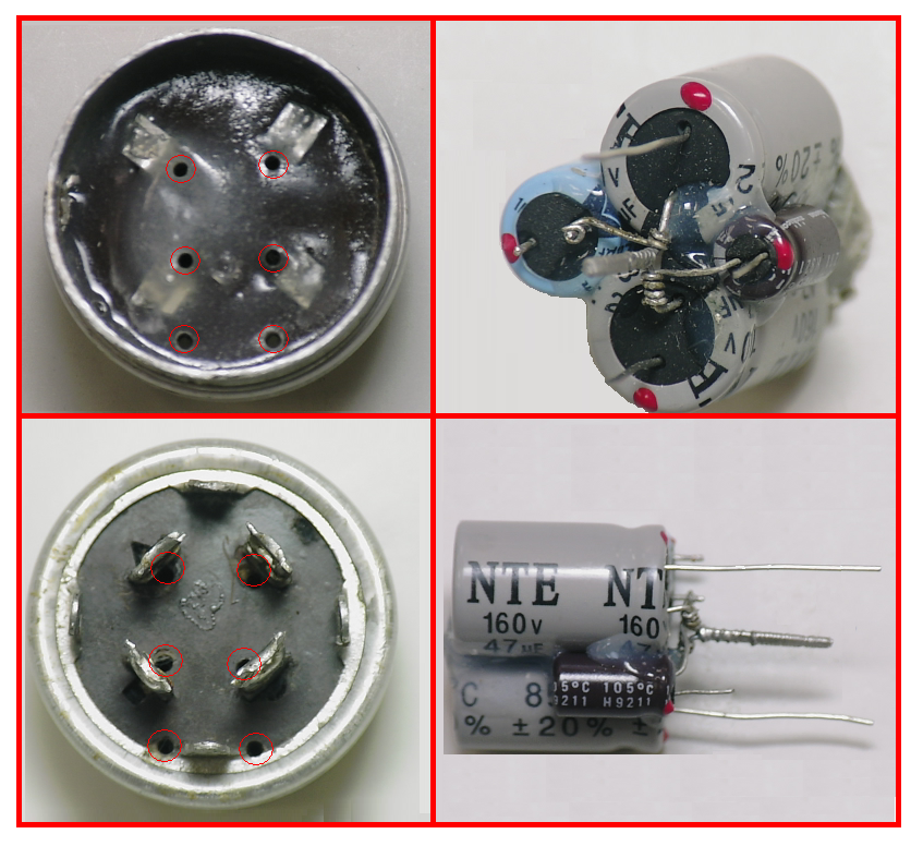 : : : : : :I go up about 1/2 of an inch from the bottom of the capacitor and either saw cut--Dremel tool cut—use tubing cutter—going completely around the capacitor can. : : :( If using a tubing cutter, it’s requiring an inner shell reforming for correcting for the operations compressed inner lip. ) : : :Unstuff the old innards, fold the aluminum interconnect tabs outward and over against the phenolic bottom plate. : : :Use a solvent for cleaning the inside to an immaculately clean state. : : :Mix up some two part clear epoxy and fill up the insides with about an 1/8 in layer on the bottom plate. :Go aside during curing time and figure out the sizing’s and arrangements of caps be acquired for the new "stuffings". : : :In my illustrations above, you are seeing three B+ filters and the smallest unit is being for a lower voltage rated, cathode bypass unit. : : :I use wrapped on and soldered leads of common RED--BLACK--YELLOW--GREEN wire that I salvaged from phone line or CAT-5 cabling. : : :Those individual stripped and tinned wire lead ends feed thru 1/16 in mini holes drilled in the caps bottom plate. : : :Considered that the epoxy has now fully cured to its hardened state, the bottom left depiction shows how I drill just beside the inside terminals and pass all the way thru to come out as is shown on the upper photo. : : :The individual wires are then fed thru and wrapped one turn around the very base of its assigned terminal and reflow soldered. : : :The ground wire enters from one hole and then gets a tight conformal turn around the very base of that tab and then passes thru the hole, both lines then go to the ground of the cap cluster . : : :Last step is to make a plastic sleeve to go inside the can , mainly for making the now two separate can parts into telescoping units for reassembly, but a bit of additional insulative precaution also. : : :My plastic source is the common clear plastic that one sees produce from the grocery store coming in as larger clamshell packaging around products. : : :Cut out a rectangle of plastic a bit longer than the inside requirement of the capacitor length, and let the other dimension ride, with it minimally being of the internal circumference of the cap. : : :Plop the plastic within the long shell of the empty cap can and fold into a circle and use multiple fingers pressure inside to have that plastic conforming to the inside shell. : : :Mark a line with a fine Sharpie where the end of the plastic would require the cutting of the excess plastic , now encircling it, in order to have a one turn plastic liner within the caps aluminum shell. : : :Pull out the marked plastic and cut a bit wider that the mark up, in order to then be able to micro trim down to a flush meeting of the butted, ends when pressure fitted within the shell. : : :Leave the plastic inside and then place on the short end terminal cap, by telescoping it around the plastic and see what the other length dimension needs to be trimmed down to. : : :Once the plastic sleeve is sized, clean out the inside surfaces of the two cap shell halves and abrade the inside 1 inch of both portions, to either side of where the cap was initially cut apart. : : :Pull of your end cap and mark around the plastic where the seam is and contact cement a 1 in wide aluminum strip that will center on that seam reference, just marked on the plastic, and have it placed on the side of the plastic that will be contacting the aluminum cap shell. : : :One then contact cement coats the long dimension of the plastic shell, stopping ~1/4 short of the just prepared aluminum foil grounding / interface strip, additionally coat the inside shell of the long dimension aluminum shell. :Wait for its set up tacky time and then wind up the plastic and form out to fit within the shell and conform to the inside shape of the shell, using finger pressure. : : :Since no cement was used on the other half of the plastic, one should then be able to use a combined slow rotating-pressing together procedure, initially, to have the end cap then telescoping onto the plastic sleeve. :That then results in holding a perfectly aligned mating of the seams of the two aluminum cans parts. : : :One then "stuffs" and wires in the new internal electrolytics and "telescopes" on the end cap and then purposefully leaves an ~ 1/16 gap that can be slightly overfilled in with a 2 piece epoxy mix; to colorize that mix, I additionally combine in either aluminum dust or a few drops of aluminum paint. : : :Let the filling cure hard and finish flush with water wetted . . . wet n' dry carborundum paper . . . using longitudinal strokes. : : :Sooooo . . . . you now know my time evolved specific procedure . . . on how I " stuffs " a Wild Bikini . . .errr . . . canned capacitor. : : : : : :73's de Edd : : : :  : |
:
:
:
:
:
:
:
:
::If a good make American radio from the 1950s or newer has electrolytics that are performing well now, they will likely continue to perform well as long as you use the radio. Some smaller older Japanese electrolytics tend to leak due to inferior rubber seals, but most of that was rectified by the early 1970s.
::
::If the radio is an AC/DC radio, where voltages are low, it is much more likely that the electrolytics will dry up and cause hum than short out and cause damage, IF they do dry up.
::
::Peter must remember that he sent me a newer model LCD to repair in which most of the electrolytics had shorted, so don't have the idea that newer electrolytics are going to out-perform all older ones.
::
::T.
::
:
:
The existing cap is not large enough to fit the three caps i need to replace. Two will fit side by side and i can stagger the large one. I can run longer insulated leads through the bottom. This radio is so dense that it is going to take some real thought to get this cap out. I like the idea of using the base plate with drilled holes. No room for a drill or my Dremell.
Will post results.
Thanks
Mitch
:Will post results.
:Thanks
:Mitch
Hi Mitch:
You realize that all 3 filter caps don't have to be physically located where the original ones were as long as they are electrically in the same spot.
For instance you see the three B+ points D, C, A... right? And the neg point "B" also.
The 70uf cap at the 100v B+ point "C" can be located anywhere physically elsewhere between that 100v B+ "C" line and the neg "B" point .
And likewise with the 40uf cap at the 90v B+ point "A".. it too can be located anywhere between that 90v B+ line and the neg point "B".
So finding physical room may be easier then you thought.
:
:
: : : : : : : : : : : : : : :Sir Mitch. . . . . et al . . . : : : :If I am finding the use of a riveted mount plate I will dimple center punch its exact center and then use incrementally increased sizes of drill sizes and usually at about the 1/8in or so sizing . . . then the two rivet halves just fallout. : : :If there is adequate working area thereabout, a cut off wheel in a Dremel tool, in taking off minute layers of a rivet head, gets you there also. : : :A pop rivet is my preferred replacement . . . insertion tool space . . . permitting. : : : :These pics show how I build up an old electrolytic's casing: : : : : : : : : : : :I go up about 1/2 of an inch from the bottom of the capacitor and either saw cut--Dremel tool cut—use tubing cutter—going completely around the capacitor can. : : :( If using a tubing cutter, it’s requiring an inner shell reforming for correcting for the operations compressed inner lip. ) : : :Unstuff the old innards, fold the aluminum interconnect tabs outward and over against the phenolic bottom plate. : : :Use a solvent for cleaning the inside to an immaculately clean state. : : :Mix up some two part clear epoxy and fill up the insides with about an 1/8 in layer on the bottom plate. :Go aside during curing time and figure out the sizing’s and arrangements of caps be acquired for the new "stuffings". : : :In my illustrations above, you are seeing three B+ filters and the smallest unit is being for a lower voltage rated, cathode bypass unit. : : :I use wrapped on and soldered leads of common RED--BLACK--YELLOW--GREEN wire that I salvaged from phone line or CAT-5 cabling. : : :Those individual stripped and tinned wire lead ends feed thru 1/16 in mini holes drilled in the caps bottom plate. : : :Considered that the epoxy has now fully cured to its hardened state, the bottom left depiction shows how I drill just beside the inside terminals and pass all the way thru to come out as is shown on the upper photo. : : :The individual wires are then fed thru and wrapped one turn around the very base of its assigned terminal and reflow soldered. : : :The ground wire enters from one hole and then gets a tight conformal turn around the very base of that tab and then passes thru the hole, both lines then go to the ground of the cap cluster . : : :Last step is to make a plastic sleeve to go inside the can , mainly for making the now two separate can parts into telescoping units for reassembly, but a bit of additional insulative precaution also. : : :My plastic source is the common clear plastic that one sees produce from the grocery store coming in as larger clamshell packaging around products. : : :Cut out a rectangle of plastic a bit longer than the inside requirement of the capacitor length, and let the other dimension ride, with it minimally being of the internal circumference of the cap. : : :Plop the plastic within the long shell of the empty cap can and fold into a circle and use multiple fingers pressure inside to have that plastic conforming to the inside shell. : : :Mark a line with a fine Sharpie where the end of the plastic would require the cutting of the excess plastic , now encircling it, in order to have a one turn plastic liner within the caps aluminum shell. : : :Pull out the marked plastic and cut a bit wider that the mark up, in order to then be able to micro trim down to a flush meeting of the butted, ends when pressure fitted within the shell. : : :Leave the plastic inside and then place on the short end terminal cap, by telescoping it around the plastic and see what the other length dimension needs to be trimmed down to. : : :Once the plastic sleeve is sized, clean out the inside surfaces of the two cap shell halves and abrade the inside 1 inch of both portions, to either side of where the cap was initially cut apart. : : :Pull of your end cap and mark around the plastic where the seam is and contact cement a 1 in wide aluminum strip that will center on that seam reference, just marked on the plastic, and have it placed on the side of the plastic that will be contacting the aluminum cap shell. : : :One then contact cement coats the long dimension of the plastic shell, stopping ~1/4 short of the just prepared aluminum foil grounding / interface strip, additionally coat the inside shell of the long dimension aluminum shell. :Wait for its set up tacky time and then wind up the plastic and form out to fit within the shell and conform to the inside shape of the shell, using finger pressure. : : :Since no cement was used on the other half of the plastic, one should then be able to use a combined slow rotating-pressing together procedure, initially, to have the end cap then telescoping onto the plastic sleeve. :That then results in holding a perfectly aligned mating of the seams of the two aluminum cans parts. : : :One then "stuffs" and wires in the new internal electrolytics and "telescopes" on the end cap and then purposefully leaves an ~ 1/16 gap that can be slightly overfilled in with a 2 piece epoxy mix; to colorize that mix, I additionally combine in either aluminum dust or a few drops of aluminum paint. : : :Let the filling cure hard and finish flush with water wetted . . . wet n' dry carborundum paper . . . using longitudinal strokes. : : :Sooooo . . . . you now know my time evolved specific procedure . . . on how I " stuffs " a Wild Bikini . . .errr . . . canned capacitor. : : : : : :73's de Edd : : : : : |
:
:
:
:
:
:
:
:
::If a good make American radio from the 1950s or newer has electrolytics that are performing well now, they will likely continue to perform well as long as you use the radio. Some smaller older Japanese electrolytics tend to leak due to inferior rubber seals, but most of that was rectified by the early 1970s.
::
::If the radio is an AC/DC radio, where voltages are low, it is much more likely that the electrolytics will dry up and cause hum than short out and cause damage, IF they do dry up.
::
::Peter must remember that he sent me a newer model LCD to repair in which most of the electrolytics had shorted, so don't have the idea that newer electrolytics are going to out-perform all older ones.
::
::T.
::
:
:
To all,
I replaced 4 more paper caps tonight, not the E's yet.
Have 6 more papers to replace in the FM circuit then the E's after much thought from your posts. I will replace the E's because my grand children may not receive these radios for some 10 to 20 years from my estate.
When i got this radio i could get one local FM station and about five AM stations. After changing some 20 + paper caps, i get some 20 FM stations very clear and AM stations around the states also very clear. With a cheap cap tester most of the paper caps did not test at all? But the results of changing these cap is great and i will change the rest of the papers and E's.
Maybe i just got lucky on this one.
Will need all of your help on the alignment on this one.
Thanks for being on the Forum
Mitch
You have a good point there about the bad caps in the monitor I gave you. but why did they fail?
That's the real question.. right?
Do we know why?
Do we know if they were under-rated for the actual applied voltage or for the temperature or something? ..
..or are you just assuming poor manufacturing?
My original point, which everyone is circumventing, is that the electrolytics are not the cause of lack of stations, and if they are working fine, why are they being replaced? This won't make the radio perform better. If the original ones are working well now, they will likely continue to work well for quite some time.
It seems that people pay more attention to popular opinion (whether proven or not) or explanations that contain lots of flourishes and fluff.
I am sure that if one throws enough new components at this radio, it may, indeed work well again, but most of the components will not be those which have solved the problem, and/or ones that were necessarily replaced.
T.
T.
:
:T.
:
(Not to completely destroy this thread.. so please excuse this diversion..)
.. interesting but Where did you get that info Thom?
I had always read that one cannot overdose on vitamin-C because the body simply allows any excess to be washed away in urine... so that's probably why folks take lots.
http://www.helium.com/items/859263-vitamin-c-overdose-symptoms