
Referring to the 1st of the illustrations 3 parts :
The shaft of the new control is cut off about 1/3 up the shafts length from the control bushing.
One then precisely measures the length of the original shaft from the point of its exit from the shaft bushing, to the shafts extreme end.
Moving over to the "stub" on the new control, you measure to see where to mark the old controls shaft, to be cut off, so that about a 1/16 of a gap will be between the conjoined shafts . . . eventually, it being infused with an epoxy bonding filler.
Referring to the 2nd of the illustrations 3 parts :
The next step is where the rotational shear integrity of the pair of conjoined shafts is acquired. There is the depicted BLACK metal filler tab which I cut from an old hacksaw or band saw materiel remnant, using a #409 cutoff wheel chucked in a Dremel tool.
The 3/16 in and the 7/16 in dimensional aspects concur with being a bit smaller than the 1/4 in control diameter and 7/16 being with the pair of 1/4 in slots having been cut across the ends of the two shaft halves. That is adequate for the epoxy filler flowing in and around the gaps. One then additionally chamfers the ends of the shafts for making room for even more epoxy filler flow in.
Now, herein, is where the procedure could take on a variance. In the case of the bandswitch, I wanted a resultant TOTALLY straight shaft co-joining and with NO eccentricity, thus the use of that lengthwise slit brass sleeve, which I then slid down over the shaft halves. That holds shafts in PERFECT true alignment, with only the oozed out epoxy "flash" left, and it needing to be filed away.
NOW, on the re- shafting of a CONTROL , with but minimal rotational torque being experienced, BUT still the need of true alignment of the two shaft halves I have used a simpler procedure of:
Examine a 2 piece clothes pin . . .
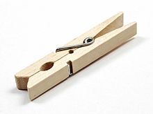
. . . and you will see the two opposing grooves that surround the clothing item and clothesline wire is approaching a 1/4 inch diameter dimension . . . (that magic number ! ) . . . when being slightly opened.
What I would do, was to enhance the limited tensioning that the original metal spring was providing , by going just in front of that spring, at those two small cross groves holding the spring ends and additionally using a multi-twirled rubber band around the two halves there to provide even a stronger clamping action, but yet, still being able to open up enough to accept the 1/4 in shaft between the wooden halves grooves.
One then takes mixed up epoxy and "butters" up the metal filler, the two shaft ends, their slits and then a small 1 in by 3 in sheet of wax paper is centered on and wrapped around the shafts , with the gripping hands thumb and index finger tightening up on the papers tabs to pull the shafts into alignment and additionally compressing epoxy down into any voids. THEN the other hand opens the clothes pin and centers it in the spliced area to compress the shaft halves into alignment while the epoxy is curing.
And BTW I was always using the "watery" " Elmers"types of two part epoxies . . . in standard conventional cure time formulations . . . instead of the thicker "hard" stick types that require their kneading together.
Refinements . . . . ?
Later in time . . . I refined upwards on the conventional clothespins grooves tolerances, by having my plunge router nearby, with a 1/4 bit straight shank router bit mounted in it and FIRMLY supporting my palms on the router table.
Then there was a slowly levered finger pressing downwards of those two wooden grooves of a clothespin, downwards into the bit, resulting in a perfect 1/4 in round shaping of the combined two halves of the clothespin.
Additionally I even went a different route in taking a 3/4 in thick scrap of maple (oak-ash-hickory, etc hardwoods) and cutting it 3 in long by 2 in wide. Then the router made a hole in the center of that 2 in dimension, but with it being but 1/2 of an inch away from one end on the 3 in length dimension.
(That logic being, such that one ends close clearance lets you STILL use that tensioning and initial aligning of the shaft halves while tightening up the grip on the wax paper sheet, had its hole been centered on that 3 in dimension, that paper treatment could not still be done.)
The block is then sawed in half with its divisional seam being in the center of the hole, you then have the two halves, with that circle being more precise, and the 3/4 in width dimension covers more area of the shafts union.
The other hand then plops the two wooden halves grooves around the shaft at the proper point and then one hand can hold them together while rubber bands are twirled around the wood ends for providing solid tensioning while the epoxy cures.
Lastly . . . . . . do compare photo 1 against 3 and you see that the new shafts dimensional integrity is maintained.
And in YOUR case, with that presence of a SPECIAL slotted AND fluted shaft transition is not one that could have been easily made otherwise.
It's not like when one merely cuts off a round shaft to make it a shorter round shaft. Nor is it the shown depiction where a round shaft becomes a half round one.
(Now . . .? . .Can YOU do a milling machine quality treatment of the transitioning of a round shaft to a half round one by mere draw filing.)
(I can, but it requires a holding jig made from a maple block with a 1/4 in hole drilled thru it and then a few precise end cuts with a table saw . . . to make a depth "stop" for the ending of initial roughing in and its eventual feathering in of draw filing strokes operations.)
I also find this procedure being useful in utilizing those more plentiful . . . and cheeeeeeper . . . short shafted controls with the screwdriver adjustment slot at the end . . . . . in its transitioning them into conventional looooonger shafted units.
Thasssit . . . .
73's de Edd

