Home  Resources  References  Tubes  Forums  Links  Support 
grundig 3165 U
10/16/2010 8:42:20 PMNeal Buddenberg
Where can I get a schematic for a Grundig 3165 U? The rubber bands that hold the ferrite bar in its bracket have disintegrated and the leads have all broken off at their soldering lugs....thanx, nb
10/18/2010 11:58:56 AMNeal Buddenberg
:Where can I get a schematic for a Grundig 3165 U? The rubber bands that hold the ferrite bar in its bracket have disintegrated and the leads have all broken off at their soldering lugs....thanx, nb
:Anybody?
10/18/2010 12:16:15 PMMitch
::Where can I get a schematic for a Grundig 3165 U? The rubber bands that hold the ferrite bar in its bracket have disintegrated and the leads have all broken off at their soldering lugs....thanx, nb
::Anybody?
:
Neal,
I found the schematic at justradios.com. They have a vast list of european schematics including your model.
It will cost a few dollars.
Mitch
10/18/2010 10:45:30 PMEdd


Sir Neal . . . . .


How many fine wires were there to break off ?. . . . and apparently fine solid wire, as I would think that Litz would be more pliant to breakage, unless in a tinned area.


Now, seems like I can certainly visualize to 4 connections to the ferrite antenna , but possinly 6, if LW band is additionally wired into it.


I may come up with its schema, but definitely NO close up photo of that area of concern.


73's de Edd


:::Where can I get a schematic for a Grundig 3165 U? The rubber bands that hold the ferrite bar in its bracket have disintegrated and the leads have all broken off at their soldering lugs....thanx, nb
:::Anybody?
::
:Neal,
:I found the schematic at justradios.com. They have a vast list of european schematics including your model.
:It will cost a few dollars.
:Mitch
:

10/20/2010 1:57:14 PMNeal Buddenberg
:
:

:
:
:
:
:
:
:
:
:
:
:Sir Neal . . . . .
:
:
:How many fine wires were there to break off ?. . . . and apparently fine solid wire, as I would think that Litz would be more pliant to breakage, unless in a tinned area.
:
:
:Now, seems like I can certainly visualize to 4 connections to the ferrite antenna , but possinly 6, if LW band is additionally wired into it.
:
:
:I may come up with its schema, but definitely NO close up photo of that area of concern.
:
:
:
:
:
:73's de Edd

:
:
:


:

:
:
:
:
:
:
:
::::Where can I get a schematic for a Grundig 3165 U? The rubber bands that hold the ferrite bar in its bracket have disintegrated and the leads have all broken off at their soldering lugs....thanx, nb
::::Anybody?
:::
:
:
:
:
::Neal,
::I found the schematic at justradios.com. They have a vast list of european schematics including your model.
::It will cost a few dollars.
::Mitch
::
:
Well, the ferrite rod itself is only 4 inches long, it has two regular coils wired in series, about an inch apart over the middle, and a honeycomb coil close to the end: |-HHH-| |-VVVVV------VVVVV-|
| ====|====|==================|
| | | |
Only 4 leads, but only 4 lugs to hook onto; no room on the ferrite bar for more coils, so I do not believe any coils are missing. You are correct, it's enamel coil wire, 28 gage, all broke off at the solder joint. Thoughts?
11/6/2010 7:47:25 PMEdd


Sir Neal . . . . .

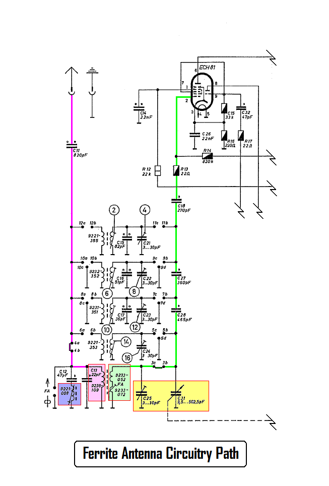
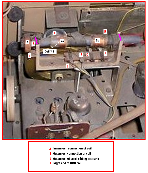
Most humble apologies for the time delay . . .I had initially prepared referencing and misplaced it . . .


I have initially prepared a thumbnail of the frontal RF area of concern with the possibility of our comparing the schematic to the leads of the intact ferrite loop antenna to get the unit operational again.


Should be no problem as, for as a minimum ONLY two leads need to get connected up initially, to make the BCB operational again.


Initially consult the schematic thumbnail below and see the [Pea Green] highlighted area, now that would be the BCB coil which resonates with the [Yellow] highlighted RF section of the tuning condenser and its paralleled companion trimming condenser. Do note that this complete inductance is made up on the surface of the ferrite rod as two separate windings.


The bulk of the winding is on the right side of the bar with a smaller winding being started over to the left on
an adjustable small coil form, The idea is for the both of them combining their series inductance to then to resonate optimally at the high end of the BCB at ~1400 kHZ . The smaller coil to the left is capable of being slid a bit laterally in either direction upon the rod, to minutely skew its inductive value.


That is then being much in the manner in which the trimmer associated with the main RF tuning condenser is doing.
The optimal setting is being found for that second (trimming) coil, and its usually then being locked down with a daub of melted wax.


Well . . .well . . . well . . . It now looks like ;


The Right Honorable and Esteemed . . . Sir Dennis Wesserling . . .Esq. . . . has now sent me a top of chassis photo of the area of concern of the " W " suffix version of that Gruuuuundig chassis of yours.

Should be the same.
I have just now done a re digitalization and brought it on up to the optimal magnification capabilities that one can attain while initially working from a low bit density J-peg format origin. . . . With you now seeing its initial onsets of some slight "coagulation" and "blistering" effects.


Now, in looking to its assigned referencing areas :


The #2 designator is for the coil just being referred to with "#2b" being the fixed section and 2a being the movable section on the clear plastic form.


Now resolution prohibits my positively seeing it, but you have the physical set AND the eyeballs and I guesstimate that my " D " assignment would be the start of that #2b winding and it getting connected to that, associative ~"D " part of the terminal strip.


There is probably a 1-2 turn spiraling of the wire connection between the #2a-b coils and then the end of the complete coil #2 windings ends at C and goes over to terminal strip ~"C".


Since we were just now at 2a coil, go back to the schema thumbnail and note that there is the small variable adjustment arrow superimposed upon that bottom 2a winding . . . of course that is being reference to the coils sliding variable adjustment to which I had earlier mentioned.


OK now lets confirm, if you have the FA ( Ferrite Antenna) button pushed, you would then have the BCB resonating two part coil and RF tuning condenser circuitry , which I just described, as being engaged.

RF SIGNAL PATH:

Your BCB received RF signal is picked up by the ferrite loop antenna proper and signal passes up [Green] mark-up path thru the switch jumper bar on section # 3 switch completing its c-b path, thus getting the tuning condenser RF section into circuit.


The signal passes thru multiple isolative, coupling capacitors until it finally reaches pin 2 of your sets mixer tube.

That’s all of the connectivity that is required to make the unit operational on the BCB.

Now, the other mode of operation would be if one additionally wants the use of an external antenna input. In that mode, the FA antenna switch is RELEASED.


That then sets up the outdoor aerial signal flowing down the [Fuscia] path and down to #4 switch, which then has a completed linking between a-b and the passage of the RF signal further on down on into the small link coupling coil depicted in the [Pale Fucsia] mark up area. That then inductively couples outdoor signal into the Ferri loop rod antenna coil circuitry.


That would then account for my showing designated coil #3? which I believe that you can see wound underneath the #2a coil.


If I am in error, due to the poor definition, check and see if my #2a and #3 assignments are reversed . . . an ohmmeter should tell all . . . .about all of the coils and windings . . . but I DON'T think that will be the case.


A coil serving a minimal function . . . . in these times


We now only have that hunk-a hunk-a lattice wound coil mounted on the very end of the ferrite rod to account for.


It, in conjunction with its companion 47pf capacitor is making a resonant trap at 468/70 Khz.


By the pic, it appears to be connecting its innermost beginning of its winding to terminal A, while the outer end of the winding is going to terminal B.

OVERALL . . . on the terminal connections to the 4 lug terminal board:

Looking at the schematic one is seeing 3 coil windings going to a common ground, so that might account for only one connection of the terminal board taking care of the common grounds, thus leaving two terminal lugs for each of the coils and one lug associated with the big trap coil which has to go downstairs to find that 47 pf cap.


Just track all of your terminal lugs wires down to see what associative components that they connect to then associate them with the schematics wiring.

The Fuscia bar mark ups on the photo are pretty close to the supports ( missing) for the ferrite rod, and if that unit was shipped and the box ever got inverted 180 degrees, I can see the whole rod falling down . . . and go boom.


PARTICULARLY if it gets tossed down in a truck while being loading in that inverted position .


73's de Edd


::
::

::
::
::
::
::
::
::
::
::
::
::Sir Neal . . . . .
::
::
::How many fine wires were there to break off ?. . . . and apparently fine solid wire, as I would think that Litz would be more pliant to breakage, unless in a tinned area.
::
::
::Now, seems like I can certainly visualize to 4 connections to the ferrite antenna , but possinly 6, if LW band is additionally wired into it.
::
::
::I may come up with its schema, but definitely NO close up photo of that area of concern.
::
::
::
::
::
::73's de Edd

::
::
::


::

::
::
::
::
::
::
::
:::::Where can I get a schematic for a Grundig 3165 U? The rubber bands that hold the ferrite bar in its bracket have disintegrated and the leads have all broken off at their soldering lugs....thanx, nb
:::::Anybody?
::::
::
::
::
::
:::Neal,
:::I found the schematic at justradios.com. They have a vast list of european schematics including your model.
:::It will cost a few dollars.
:::Mitch
:::
::
:Well, the ferrite rod itself is only 4 inches long, it has two regular coils wired in series, about an inch apart over the middle, and a honeycomb coil close to the end: |-HHH-| |-VVVVV------VVVVV-|
: | ====|====|==================|
: | | | |
:Only 4 leads, but only 4 lugs to hook onto; no room on the ferrite bar for more coils, so I do not believe any coils are missing. You are correct, it's enamel coil wire, 28 gage, all broke off at the solder joint. Thoughts?
:


© 1989-2025, Nostalgia Air