Tom:
Yes, the thingy mounted on the speaker is the output transformer, snd the output tube has a 7000 Ohm plate impedance, and I'll have to assume a four Ohm speaker voice coil. Therefore, if the transformer is bad, you will need a 7K to 4 Ohm transformer.
Lewis
:
:
:
:
:Tom:
:Yes, the thingy mounted on the speaker is the output transformer, snd the output tube has a 7000 Ohm plate impedance, and I'll have to assume a four Ohm speaker voice coil. Therefore, if the transformer is bad, you will need a 7K to 4 Ohm transformer.
:Lewis
Lewis, Thanks a lot -- that's exactly what I needed to know. Tom
::
:
::
::
::
::Tom:
::Yes, the thingy mounted on the speaker is the output transformer, snd the output tube has a 7000 Ohm plate impedance, and I'll have to assume a four Ohm speaker voice coil. Therefore, if the transformer is bad, you will need a 7K to 4 Ohm transformer.
::Lewis
:
:Lewis, Thanks a lot -- that's exactly what I needed to know. Tom
Tom:
If you will Google "Audio output transformer impedance" you will findd a site that will tell you all you need to know including tube impedances.
Lewis
:::
::
:
:::
:::
:::
:::Tom:
:::Yes, the thingy mounted on the speaker is the output transformer, snd the output tube has a 7000 Ohm plate impedance, and I'll have to assume a four Ohm speaker voice coil. Therefore, if the transformer is bad, you will need a 7K to 4 Ohm transformer.
:::Lewis
::
::Lewis, Thanks a lot -- that's exactly what I needed to know. Tom
:
:
:
:Tom:
:If you will Google "Audio output transformer impedance" you will findd a site that will tell you all you need to know including tube impedances.
:Lewis
:
Hi Lewis:
Just started to replace the capacitors in this Crosley and ran into another issue. I'm just a novice and have fixed maybe 10-15 tube radios and recapped the units and so on without a problem. This unit has two rectangular capacitor boxes attached to the chassis; one has two solder lugs on each end and the other a set of lugs on one end only. I'm assuming these are electrolytics as I see no other beefy caps in the set. BUT, the values don't seem right and the polarity is not marked. The double lugged one say 4-8 mfd and the single lugged one says .5-.5 and that metal container is directly grounded--using a lug under the rivet. I'm really confused now -- are these both electrolytics, and what would the polarity be??
Hoping you can shed light on this but I don't want to impose either. I've done an exhaustive search on this model and nothing technical comes up to help me. Thanks again, and for the tip on Output transformers -- Tom
:
:
:
:
::::
:::
::
:
Tom:
Your B+ will come from the filament of the type 80 rectifier, then go to the 8uFd. capacitor, then to the speaker field, then to the bottom right connection of the speaker plug, here it splits, with one leg going through the primary of the output transformer, the other to the screen of the output tube, type 47. After going through the field coil, it goes to the six microFarad cap. These seem to be in a box marked W23801, what is what I think you're looking at. There is another box containing caps marked W22412 on the schematic, which looks like it contains two .1 caps. Your B- Voltage comes from the center tap of the transformer winding that goes to the plates of the type 80 tube. Maybe this will help you determine the polarity of the filter capacitor terminals.
Lewis
::::
::::
::::
::::Tom:
::::Yes, the thingy mounted on the speaker is the output transformer, snd the output tube has a 7000 Ohm plate impedance, and I'll have to assume a four Ohm speaker voice coil. Therefore, if the transformer is bad, you will need a 7K to 4 Ohm transformer.
::::Lewis
:::
:::Lewis, Thanks a lot -- that's exactly what I needed to know. Tom
::
::
::
::Tom:
::If you will Google "Audio output transformer impedance" you will findd a site that will tell you all you need to know including tube impedances.
::Lewis
::
:Hi Lewis:
:Just started to replace the capacitors in this Crosley and ran into another issue. I'm just a novice and have fixed maybe 10-15 tube radios and recapped the units and so on without a problem. This unit has two rectangular capacitor boxes attached to the chassis; one has two solder lugs on each end and the other a set of lugs on one end only. I'm assuming these are electrolytics as I see no other beefy caps in the set. BUT, the values don't seem right and the polarity is not marked. The double lugged one say 4-8 mfd and the single lugged one says .5-.5 and that metal container is directly grounded--using a lug under the rivet. I'm really confused now -- are these both electrolytics, and what would the polarity be??
:Hoping you can shed light on this but I don't want to impose either. I've done an exhaustive search on this model and nothing technical comes up to help me. Thanks again, and for the tip on Output transformers -- Tom
:
::
::
::
::
:::::
::::
:::
::
:
Using the words of Paris Hilton, just below: The following potential candidates are showing up: 4577-017 OUTPUT UNK 430V088H06 SP (6-7K Z) TO 3.2 VC, 1-3 WATTS, FIG 3, NEW.............. 2 1 7/8 1 3/8 1 1/8 . . . . . . . . . . .$3.00 Thasssit . . . . . |
Re Worked Schema as a Crosley 125 Mark Up:  |
:Tom:
Hi. I'm looking at restoration on a Crosley Model 125. I've never seen a speaker setup quite like this -- I take it from the schematic that the big rectangular piece is a transformer of some type? If so, does anyone perhaps know the value of it? Thanks a lot! Tom
:
:
:Your B+ will come from the filament of the type 80 rectifier, then go to the 8uFd. capacitor, then to the speaker field, then to the bottom right connection of the speaker plug, here it splits, with one leg going through the primary of the output transformer, the other to the screen of the output tube, type 47. After going through the field coil, it goes to the six microFarad cap. These seem to be in a box marked W23801, what is what I think you're looking at. There is another box containing caps marked W22412 on the schematic, which looks like it contains two .1 caps. Your B- Voltage comes from the center tap of the transformer winding that goes to the plates of the type 80 tube. Maybe this will help you determine the polarity of the filter capacitor terminals.
:Lewis
:
:
:
:::::
:::::
:::::
:::::Tom:
:::::Yes, the thingy mounted on the speaker is the output transformer, snd the output tube has a 7000 Ohm plate impedance, and I'll have to assume a four Ohm speaker voice coil. Therefore, if the transformer is bad, you will need a 7K to 4 Ohm transformer.
:::::Lewis
::::
::::Lewis, Thanks a lot -- that's exactly what I needed to know. Tom
:::
:::
:::Tom:
:::If you will Google "Audio output transformer impedance" you will findd a site that will tell you all you need to know including tube impedances.
:::Lewis
:::
::Hi Lewis:
::Just started to replace the capacitors in this Crosley and ran into another issue. I'm just a novice and have fixed maybe 10-15 tube radios and recapped the units and so on without a problem. This unit has two rectangular capacitor boxes attached to the chassis; one has two solder lugs on each end and the other a set of lugs on one end only. I'm assuming these are electrolytics as I see no other beefy caps in the set. BUT, the values don't seem right and the polarity is not marked. The double lugged one say 4-8 mfd and the single lugged one says .5-.5 and that metal container is directly grounded--using a lug under the rivet. I'm really confused now -- are these both electrolytics, and what would the polarity be??
::Hoping you can shed light on this but I don't want to impose either. I've done an exhaustive search on this model and nothing technical comes up to help me. Thanks again, and for the tip on Output transformers -- Tom
::
:::
:::
:::
:::
::::::
:::::
::::
:::
::
:
:
:
: : : :  : : : : : : :Sir Tom. . . . . : : :Utilizing your initial info of: : : : :This unit has two rectangular capacitor boxes attached to the chassis; one has two solder lugs on each end and the other a set of lugs on one end only. I'm assuming these are electrolytics as I see no other beefy caps in the set. BUT, the values don't seem right and the polarity is not marked. The double lugged one say 4-8 mfd and the single lugged one says .5-.5 and that metal container is directly grounded--using a lug under the rivet. I'm really confused now -- are these both electrolytics, and what would the polarity be?? : : : :As per your other "mystery" componets, looks like you might have found yourself some " bathtub " capacitors . . . not fiberglass . . . not white porcelain clad steel / iron . . . but metal encased ones with their use of a common grounding shell . . thus their hardware bolting / or / sometimes being riveted to the chassis. : : :You particularly mention the dual .5 mfd unit which I have marked up in [Blue-Green] and I do believe we have that one aspect nailed ! : : :But, on the schema, I am also seeing the shared part number referencing of what should be another bathtub unit with what looks to be 4 sections of .1 ufd units in the [Orange] markups. That would be 4 outer lugs for the active end of the caps with all of their opposite end leads getting connected internally within the common shell for the shells outer chassis mounting lugs to receive a grounding. : : :Then there are the mentioned filter caps, which I have further polarized for you on the schema in the [Yellow] box, and if they were marked 8 mfd and 6 mfd on the old unit, you have confirmed that unit. : : :Just for familiarizing you visually with "bathtubs", additionally . . . refer to these photos: : : :3 Section bathtub: : : : : 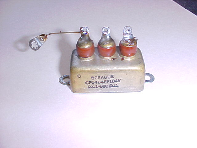 : : : : :Top/side view of bathtub: : : : :  : : : : :Bathtubs being restuffed: : : : :  : : : : : : : :I have placed a, clarified, Cross-legged 125 schema down at the very-very bottom : : :On it the separate sections of the quad 0.1 mfd units are in [Orange ] : : :The all critical audio coupling capacitor . . . which you may have already replaced . . is in [ Light Green ] : : :The audio output transformer is now showing a MORE realistic secondary turns winding, as well as the speakers voice coil winding. :The whole unit is still in the schemas top right corner, in [ Yellow ]. : : :The provided voltage specs, give you an idea that a 450 VDC rating on your filters would give you a safety cushion. : : :If you are needing ? ? ? an output transformer, in my checking of my Excel spreadsheet of this sites inventory. : : : :Using the words of Paris Hilton, just below: : : : : :> > > < < < : : : :The following potential candidates are showing up: : : : :4577-017 OUTPUT UNK 430V088H06 SP (6-7K Z) TO 3.2 VC, 1-3 WATTS, FIG 3, NEW.............. 2 1 7/8 1 3/8 1 1/8 . . . . . . . . . . .$3.00 : : : : :4543-325 OUTPUT UNKNOWN 80-1721A SP, RATIO 45:1 = 6.5K @ 3.2 VC, 8 WATTS , FIG 3, USED.... 1 2 3/4 1 5/8 1 3/8 . . . .$4.00 : : : : :1404-415 OUTPUT CROSLEY 1503 SP (7K Z) 2A5 TUBE, 5 WATTS?, MODEL 168, FIG 3, USED...... 1 3 1/8 2 0/0 1 1/2 . . . . . . . .$5.00 : : : : :4543-316 OUTPUT UNKNOWN 21J75 SP, 46:1 RATIO, ABOUT 6.8K Z @3.2 VC,1-3 WATTS, FIG 3, USD 1 2 3/8 1 3/8 1 1/8 . . . .$2.00 : : : : :4566-278 OUTPUT PHILCO 2585 P-P (1/2 OPEN, USE AS SP 42/6F6, MODEL 640, F3 TOP LUGS, U 1 3 1/2 2 0/0 1 1/2 . . . . . . . . .$3.00 : : : : :And there is an RCA # 36505 . . . but it doesn't have enough "ooomph". : : : : :Heavy transformers can be shipped relatively cheap by using the USPS's Flat Rate Priority Boxes. : : :Average cost for Medium size box is only $10.70 with no weight limit !!! . . . on BIG power transformers . . .but just how hefty is an output transformer . . . except possibly for a 30-50 watt behemoth ? : : : :Thasssit . . . . . : : : : :73's de Edd : : :  : |
:
:
:
:
:
:
:
: : : : Re Worked Schema as a Crosley 125 Mark Up: : : : : : : : : : |
:
:
:
:
:
:
:
:
:
:Hi. I'm looking at restoration on a Crosley Model 125. I've never seen a speaker setup quite like this -- I take it from the schematic that the big rectangular piece is a transformer of some type? If so, does anyone perhaps know the value of it? Thanks a lot! Tom
::
::
:
:
:
:
::Tom:
::Your B+ will come from the filament of the type 80 rectifier, then go to the 8uFd. capacitor, then to the speaker field, then to the bottom right connection of the speaker plug, here it splits, with one leg going through the primary of the output transformer, the other to the screen of the output tube, type 47. After going through the field coil, it goes to the six microFarad cap. These seem to be in a box marked W23801, what is what I think you're looking at. There is another box containing caps marked W22412 on the schematic, which looks like it contains two .1 caps. Your B- Voltage comes from the center tap of the transformer winding that goes to the plates of the type 80 tube. Maybe this will help you determine the polarity of the filter capacitor terminals.
::Lewis
::
::
::
::::::
::::::
::::::
::::::Tom:
::::::Yes, the thingy mounted on the speaker is the output transformer, snd the output tube has a 7000 Ohm plate impedance, and I'll have to assume a four Ohm speaker voice coil. Therefore, if the transformer is bad, you will need a 7K to 4 Ohm transformer.
::::::Lewis
:
:
:
:
:::::
:::::Lewis, Thanks a lot -- that's exactly what I needed to know. Tom
::::
:
::::
::::Tom:
::::If you will Google "Audio output transformer impedance" you will findd a site that will tell you all you need to know including tube impedances.
::::Lewis
:
:
::::
:::Hi Lewis:
:::Just started to replace the capacitors in this Crosley and ran into another issue. I'm just a novice and have fixed maybe 10-15 tube radios and recapped the units and so on without a problem. This unit has two rectangular capacitor boxes attached to the chassis; one has two solder lugs on each end and the other a set of lugs on one end only. I'm assuming these are electrolytics as I see no other beefy caps in the set. BUT, the values don't seem right and the polarity is not marked. The double lugged one say 4-8 mfd and the single lugged one says .5-.5 and that metal container is directly grounded--using a lug under the rivet. I'm really confused now -- are these both electrolytics, and what would the polarity be??
:::Hoping you can shed light on this but I don't want to impose either. I've done an exhaustive search on this model and nothing technical comes up to help me. Thanks again, and for the tip on Output transformers -- Tom
:::
::::
::::Just checked into the forum -- thanks so much to Lewis and Edd -- wow! In a few minutes I'm back to my humble bench to get back to work. THANKS AGAIN -- I really appreciate it!! I will give an update soon. Tom
::::
::::
:::::::
::::::
:::::
::::
:::
::
:
:

:
:
:
:
:
:
:
:
:
:
:
:
:
:Sir Tom. . . . .
:
:
:Utilizing your initial info of:
:
:
:
:This unit has two rectangular capacitor boxes attached to the chassis; one has two solder lugs on each end and the other a set of lugs on one end only. I'm assuming these are electrolytics as I see no other beefy caps in the set. BUT, the values don't seem right and the polarity is not marked. The double lugged one say 4-8 mfd and the single lugged one says .5-.5 and that metal container is directly grounded--using a lug under the rivet. I'm really confused now -- are these both electrolytics, and what would the polarity be??
:
:
:
:As per your other "mystery" componets, looks like you might have found yourself some " bathtub " capacitors . . . not fiberglass . . . not white porcelain clad steel / iron . . . but metal encased ones with their use of a common grounding shell . . thus their hardware bolting / or / sometimes being riveted to the chassis.
:
:
:You particularly mention the dual .5 mfd unit which I have marked up in [Blue-Green] and I do believe we have that one aspect nailed !
:
:
:But, on the schema, I am also seeing the shared part number referencing of what should be another bathtub unit with what looks to be 4 sections of .1 ufd units in the [Orange] markups. That would be 4 outer lugs for the active end of the caps with all of their opposite end leads getting connected internally within the common shell for the shells outer chassis mounting lugs to receive a grounding.
:
:
:Then there are the mentioned filter caps, which I have further polarized for you on the schema in the [Yellow] box, and if they were marked 8 mfd and 6 mfd on the old unit, you have confirmed that unit.
:
:
:Just for familiarizing you visually with "bathtubs", additionally . . . refer to these photos:
:
:
:3 Section bathtub:
:
:
:
:
:
:
:
:
:Top/side view of bathtub:
:
:
:
:
:
:
:
:
:Bathtubs being restuffed:
:
:
:
:
:
:
:
:
:
:
:
:I have placed a, clarified, Cross-legged 125 schema down at the very-very bottom
:
:
:On it the separate sections of the quad 0.1 mfd units are in [Orange ]
:
:
:The all critical audio coupling capacitor . . . which you may have already replaced . . is in [ Light Green ]
:
:
:The audio output transformer is now showing a MORE realistic secondary turns winding, as well as the speakers voice coil winding.
:The whole unit is still in the schemas top right corner, in [ Yellow ].
:
:
:The provided voltage specs, give you an idea that a 450 VDC rating on your filters would give you a safety cushion.
:
:
:If you are needing ? ? ? an output transformer, in my checking of my Excel spreadsheet of this sites inventory.
:
:
:
:Using the words of Paris Hilton, just below:
:
:
:
:
:> > > < < <
:
:
:
:The following potential candidates are showing up:
:
:
:
:4577-017 OUTPUT UNK 430V088H06 SP (6-7K Z) TO 3.2 VC, 1-3 WATTS, FIG 3, NEW.............. 2 1 7/8 1 3/8 1 1/8 . . . . . . . . . . .$3.00
:
:
:
:
:4543-325 OUTPUT UNKNOWN 80-1721A SP, RATIO 45:1 = 6.5K @ 3.2 VC, 8 WATTS , FIG 3, USED.... 1 2 3/4 1 5/8 1 3/8 . . . .$4.00
:
:
:
:
:1404-415 OUTPUT CROSLEY 1503 SP (7K Z) 2A5 TUBE, 5 WATTS?, MODEL 168, FIG 3, USED...... 1 3 1/8 2 0/0 1 1/2 . . . . . . . .$5.00
:
:
:
:
:4543-316 OUTPUT UNKNOWN 21J75 SP, 46:1 RATIO, ABOUT 6.8K Z @3.2 VC,1-3 WATTS, FIG 3, USD 1 2 3/8 1 3/8 1 1/8 . . . .$2.00
:
:
:
:
:4566-278 OUTPUT PHILCO 2585 P-P (1/2 OPEN, USE AS SP 42/6F6, MODEL 640, F3 TOP LUGS, U 1 3 1/2 2 0/0 1 1/2 . . . . . . . . .$3.00
:
:
:
:
:And there is an RCA # 36505 . . . but it doesn't have enough "ooomph".
:
:
:
:
:Heavy transformers can be shipped relatively cheap by using the USPS's Flat Rate Priority Boxes.
:
:
:Average cost for Medium size box is only $10.70 with no weight limit !!! . . . on BIG power transformers . . .but just how hefty is an output transformer . . . except possibly for a 30-50 watt behemoth ?
:
:
:
:Thasssit . . . . .
:
:
:
:
:73's de Edd
:
:
:
:
:
:
:
:
:
:
:
:
:
:
: Re Worked Schema as a Crosley 125 Mark Up:
:
:
:
:
:
:
:
:
:
:
:
:
:
:
:
:
:
:
:Hi. I'm looking at restoration on a Crosley Model 125. I've never seen a speaker setup quite like this -- I take it from the schematic that the big rectangular piece is a transformer of some type? If so, does anyone perhaps know the value of it? Thanks a lot! Tom
::
::
:
:
:
:
::Tom:
::Your B+ will come from the filament of the type 80 rectifier, then go to the 8uFd. capacitor, then to the speaker field, then to the bottom right connection of the speaker plug, here it splits, with one leg going through the primary of the output transformer, the other to the screen of the output tube, type 47. After going through the field coil, it goes to the six microFarad cap. These seem to be in a box marked W23801, what is what I think you're looking at. There is another box containing caps marked W22412 on the schematic, which looks like it contains two .1 caps. Your B- Voltage comes from the center tap of the transformer winding that goes to the plates of the type 80 tube. Maybe this will help you determine the polarity of the filter capacitor terminals.
::Lewis
::
::
::
::::::
::::::
::::::
::::::Tom:
::::::Yes, the thingy mounted on the speaker is the output transformer, snd the output tube has a 7000 Ohm plate impedance, and I'll have to assume a four Ohm speaker voice coil. Therefore, if the transformer is bad, you will need a 7K to 4 Ohm transformer.
::::::Lewis
:
:
:
:
:::::
:::::Lewis, Thanks a lot -- that's exactly what I needed to know. Tom
::::
:
::::
::::Tom:
::::If you will Google "Audio output transformer impedance" you will findd a site that will tell you all you need to know including tube impedances.
::::Lewis
:
:
::::
:::Hi Lewis:
:::Just started to replace the capacitors in this Crosley and ran into another issue. I'm just a novice and have fixed maybe 10-15 tube radios and recapped the units and so on without a problem. This unit has two rectangular capacitor boxes attached to the chassis; one has two solder lugs on each end and the other a set of lugs on one end only. I'm assuming these are electrolytics as I see no other beefy caps in the set. BUT, the values don't seem right and the polarity is not marked. The double lugged one say 4-8 mfd and the single lugged one says .5-.5 and that metal container is directly grounded--using a lug under the rivet. I'm really confused now -- are these both electrolytics, and what would the polarity be??
:::Hoping you can shed light on this but I don't want to impose either. I've done an exhaustive search on this model and nothing technical comes up to help me. Thanks again, and for the tip on Output transformers -- Tom
:::
::::
::::
::::
::::
:::::::
::::::
:::::
::::
:::
::
:
:Hi. Well, I removed the two bathtubs and installed the 6 new caps. The box I thought was originally the electrolytics was in fact the 4-0.1 capacitor box. I saw no electrolytics (a 4 and 6 is called for) anywhere on the chassis and discovered the box that held them had been removed at some point in time. I see where the box was and attached with two lugs and have been looking at the schematic and trying to determine the connection point for these. Can anyone cite the proper connection point for these -- I am attaching two photos. Thanks, Tom!
::
::
:
:
::
::
::
::
::
::
::
::
::
::
::
::
::Sir Tom. . . . .
::
::
::Utilizing your initial info of:
::
::
::
::This unit has two rectangular capacitor boxes attached to the chassis; one has two solder lugs on each end and the other a set of lugs on one end only. I'm assuming these are electrolytics as I see no other beefy caps in the set. BUT, the values don't seem right and the polarity is not marked. The double lugged one say 4-8 mfd and the single lugged one says .5-.5 and that metal container is directly grounded--using a lug under the rivet. I'm really confused now -- are these both electrolytics, and what would the polarity be??
::
::
::
::As per your other "mystery" componets, looks like you might have found yourself some " bathtub " capacitors . . . not fiberglass . . . not white porcelain clad steel / iron . . . but metal encased ones with their use of a common grounding shell . . thus their hardware bolting / or / sometimes being riveted to the chassis.
::
::
::You particularly mention the dual .5 mfd unit which I have marked up in [Blue-Green] and I do believe we have that one aspect nailed !
::
::
::But, on the schema, I am also seeing the shared part number referencing of what should be another bathtub unit with what looks to be 4 sections of .1 ufd units in the [Orange] markups. That would be 4 outer lugs for the active end of the caps with all of their opposite end leads getting connected internally within the common shell for the shells outer chassis mounting lugs to receive a grounding.
::
::
::Then there are the mentioned filter caps, which I have further polarized for you on the schema in the [Yellow] box, and if they were marked 8 mfd and 6 mfd on the old unit, you have confirmed that unit.
::
::
::Just for familiarizing you visually with "bathtubs", additionally . . . refer to these photos:
::
::
::3 Section bathtub:
::
::
::
::
::
::
::
::
::Top/side view of bathtub:
::
::
::
::
::
::
::
::
::Bathtubs being restuffed:
::
::
::
::
::
::
::
::
::
::
::
::I have placed a, clarified, Cross-legged 125 schema down at the very-very bottom
::
::
::On it the separate sections of the quad 0.1 mfd units are in [Orange ]
::
::
::The all critical audio coupling capacitor . . . which you may have already replaced . . is in [ Light Green ]
::
::
::The audio output transformer is now showing a MORE realistic secondary turns winding, as well as the speakers voice coil winding.
::The whole unit is still in the schemas top right corner, in [ Yellow ].
::
::
::The provided voltage specs, give you an idea that a 450 VDC rating on your filters would give you a safety cushion.
::
::
::If you are needing ? ? ? an output transformer, in my checking of my Excel spreadsheet of this sites inventory.
::
::
::
::Using the words of Paris Hilton, just below:
::
::
::
::
::> > > < < <
::
::
::
::The following potential candidates are showing up:
::
::
::
::4577-017 OUTPUT UNK 430V088H06 SP (6-7K Z) TO 3.2 VC, 1-3 WATTS, FIG 3, NEW.............. 2 1 7/8 1 3/8 1 1/8 . . . . . . . . . . .$3.00
::
::
::
::
::4543-325 OUTPUT UNKNOWN 80-1721A SP, RATIO 45:1 = 6.5K @ 3.2 VC, 8 WATTS , FIG 3, USED.... 1 2 3/4 1 5/8 1 3/8 . . . .$4.00
::
::
::
::
::1404-415 OUTPUT CROSLEY 1503 SP (7K Z) 2A5 TUBE, 5 WATTS?, MODEL 168, FIG 3, USED...... 1 3 1/8 2 0/0 1 1/2 . . . . . . . .$5.00
::
::
::
::
::4543-316 OUTPUT UNKNOWN 21J75 SP, 46:1 RATIO, ABOUT 6.8K Z @3.2 VC,1-3 WATTS, FIG 3, USD 1 2 3/8 1 3/8 1 1/8 . . . .$2.00
::
::
::
::
::4566-278 OUTPUT PHILCO 2585 P-P (1/2 OPEN, USE AS SP 42/6F6, MODEL 640, F3 TOP LUGS, U 1 3 1/2 2 0/0 1 1/2 . . . . . . . . .$3.00
::
::
::
::
::And there is an RCA # 36505 . . . but it doesn't have enough "ooomph".
::
::
::
::
::Heavy transformers can be shipped relatively cheap by using the USPS's Flat Rate Priority Boxes.
::
::
::Average cost for Medium size box is only $10.70 with no weight limit !!! . . . on BIG power transformers . . .but just how hefty is an output transformer . . . except possibly for a 30-50 watt behemoth ?
::
::
::
::Thasssit . . . . .
::
::
::
::
::73's de Edd
::
::
::
::
::
::
::
::
::
::
::
::
::
::
:: Re Worked Schema as a Crosley 125 Mark Up:
::
::
::
::
::
::
::
::
::
::
::
::
::
::
::
::
::
::
::Hi. I'm looking at restoration on a Crosley Model 125. I've never seen a speaker setup quite like this -- I take it from the schematic that the big rectangular piece is a transformer of some type? If so, does anyone perhaps know the value of it? Thanks a lot! Tom
:::
:::
::
::
::
::
:::Tom:
:::Your B+ will come from the filament of the type 80 rectifier, then go to the 8uFd. capacitor, then to the speaker field, then to the bottom right connection of the speaker plug, here it splits, with one leg going through the primary of the output transformer, the other to the screen of the output tube, type 47. After going through the field coil, it goes to the six microFarad cap. These seem to be in a box marked W23801, what is what I think you're looking at. There is another box containing caps marked W22412 on the schematic, which looks like it contains two .1 caps. Your B- Voltage comes from the center tap of the transformer winding that goes to the plates of the type 80 tube. Maybe this will help you determine the polarity of the filter capacitor terminals.
:::Lewis
:::
:::
:::
:::::::
:::::::
:::::::
:::::::Tom:
:::::::Yes, the thingy mounted on the speaker is the output transformer, snd the output tube has a 7000 Ohm plate impedance, and I'll have to assume a four Ohm speaker voice coil. Therefore, if the transformer is bad, you will need a 7K to 4 Ohm transformer.
:::::::Lewis
::
::
::
::
::::::
::::::Lewis, Thanks a lot -- that's exactly what I needed to know. Tom
:::::
::
:::::
:::::Tom:
:::::If you will Google "Audio output transformer impedance" you will findd a site that will tell you all you need to know including tube impedances.
:::::Lewis
::
::
:::::
::::Hi Lewis:
::::Just started to replace the capacitors in this Crosley and ran into another issue. I'm just a novice and have fixed maybe 10-15 tube radios and recapped the units and so on without a problem. This unit has two rectangular capacitor boxes attached to the chassis; one has two solder lugs on each end and the other a set of lugs on one end only. I'm assuming these are electrolytics as I see no other beefy caps in the set. BUT, the values don't seem right and the polarity is not marked. The double lugged one say 4-8 mfd and the single lugged one says .5-.5 and that metal container is directly grounded--using a lug under the rivet. I'm really confused now -- are these both electrolytics, and what would the polarity be??
::::Hoping you can shed light on this but I don't want to impose either. I've done an exhaustive search on this model and nothing technical comes up to help me. Thanks again, and for the tip on Output transformers -- Tom
::::
:::::
:::::
:::::
:::::
::::::::
:::::::
::::::
:::::
::::
:::
::
:
( IF 60+ year wire colorization is STILL being retained, one woud expect the plate wire to be color coded as BLUE and the just mentioned wire to be coded as RED . . . if all wiring is being in accordance to scripture.) |
Forgot to mention: The original can was attached to the chassis at the top of the pictures -- the brown shaded portion. And, the switch was rusted shut so I have temporarily just ran the 100 direct to the transformer.
:
::Hi. Well, I removed the two bathtubs and installed the 6 new caps. The box I thought was originally the electrolytics was in fact the 4-0.1 capacitor box. I saw no electrolytics (a 4 and 6 is called for) anywhere on the chassis and discovered the box that held them had been removed at some point in time. I see where the box was and attached with two lugs and have been looking at the schematic and trying to determine the connection point for these. Can anyone cite the proper connection point for these -- I am attaching two photos. Thanks, Tom!
:::
:::
::
::
:::
:::
:::
:::
:::
:::
:::
:::
:::
:::
:::
:::
:::Sir Tom. . . . .
:::
:::
:::Utilizing your initial info of:
:::
:::
:::
:::This unit has two rectangular capacitor boxes attached to the chassis; one has two solder lugs on each end and the other a set of lugs on one end only. I'm assuming these are electrolytics as I see no other beefy caps in the set. BUT, the values don't seem right and the polarity is not marked. The double lugged one say 4-8 mfd and the single lugged one says .5-.5 and that metal container is directly grounded--using a lug under the rivet. I'm really confused now -- are these both electrolytics, and what would the polarity be??
:::
:::
:::
:::As per your other "mystery" componets, looks like you might have found yourself some " bathtub " capacitors . . . not fiberglass . . . not white porcelain clad steel / iron . . . but metal encased ones with their use of a common grounding shell . . thus their hardware bolting / or / sometimes being riveted to the chassis.
:::
:::
:::You particularly mention the dual .5 mfd unit which I have marked up in [Blue-Green] and I do believe we have that one aspect nailed !
:::
:::
:::But, on the schema, I am also seeing the shared part number referencing of what should be another bathtub unit with what looks to be 4 sections of .1 ufd units in the [Orange] markups. That would be 4 outer lugs for the active end of the caps with all of their opposite end leads getting connected internally within the common shell for the shells outer chassis mounting lugs to receive a grounding.
:::
:::
:::Then there are the mentioned filter caps, which I have further polarized for you on the schema in the [Yellow] box, and if they were marked 8 mfd and 6 mfd on the old unit, you have confirmed that unit.
:::
:::
:::Just for familiarizing you visually with "bathtubs", additionally . . . refer to these photos:
:::
:::
:::3 Section bathtub:
:::
:::
:::
:::
:::
:::
:::
:::
:::Top/side view of bathtub:
:::
:::
:::
:::
:::
:::
:::
:::
:::Bathtubs being restuffed:
:::
:::
:::
:::
:::
:::
:::
:::
:::
:::
:::
:::I have placed a, clarified, Cross-legged 125 schema down at the very-very bottom
:::
:::
:::On it the separate sections of the quad 0.1 mfd units are in [Orange ]
:::
:::
:::The all critical audio coupling capacitor . . . which you may have already replaced . . is in [ Light Green ]
:::
:::
:::The audio output transformer is now showing a MORE realistic secondary turns winding, as well as the speakers voice coil winding.
:::The whole unit is still in the schemas top right corner, in [ Yellow ].
:::
:::
:::The provided voltage specs, give you an idea that a 450 VDC rating on your filters would give you a safety cushion.
:::
:::
:::If you are needing ? ? ? an output transformer, in my checking of my Excel spreadsheet of this sites inventory.
:::
:::
:::
:::Using the words of Paris Hilton, just below:
:::
:::
:::
:::
:::> > > < < <
:::
:::
:::
:::The following potential candidates are showing up:
:::
:::
:::
:::4577-017 OUTPUT UNK 430V088H06 SP (6-7K Z) TO 3.2 VC, 1-3 WATTS, FIG 3, NEW.............. 2 1 7/8 1 3/8 1 1/8 . . . . . . . . . . .$3.00
:::
:::
:::
:::
:::4543-325 OUTPUT UNKNOWN 80-1721A SP, RATIO 45:1 = 6.5K @ 3.2 VC, 8 WATTS , FIG 3, USED.... 1 2 3/4 1 5/8 1 3/8 . . . .$4.00
:::
:::
:::
:::
:::1404-415 OUTPUT CROSLEY 1503 SP (7K Z) 2A5 TUBE, 5 WATTS?, MODEL 168, FIG 3, USED...... 1 3 1/8 2 0/0 1 1/2 . . . . . . . .$5.00
:::
:::
:::
:::
:::4543-316 OUTPUT UNKNOWN 21J75 SP, 46:1 RATIO, ABOUT 6.8K Z @3.2 VC,1-3 WATTS, FIG 3, USD 1 2 3/8 1 3/8 1 1/8 . . . .$2.00
:::
:::
:::
:::
:::4566-278 OUTPUT PHILCO 2585 P-P (1/2 OPEN, USE AS SP 42/6F6, MODEL 640, F3 TOP LUGS, U 1 3 1/2 2 0/0 1 1/2 . . . . . . . . .$3.00
:::
:::
:::
:::
:::And there is an RCA # 36505 . . . but it doesn't have enough "ooomph".
:::
:::
:::
:::
:::Heavy transformers can be shipped relatively cheap by using the USPS's Flat Rate Priority Boxes.
:::
:::
:::Average cost for Medium size box is only $10.70 with no weight limit !!! . . . on BIG power transformers . . .but just how hefty is an output transformer . . . except possibly for a 30-50 watt behemoth ?
:::
:::
:::
:::Thasssit . . . . .
:::
:::
:::
:::
:::73's de Edd
:::
:::
:::
:::
:::
:::
:::
:::
:::
:::
:::
:::
:::
:::
::: Re Worked Schema as a Crosley 125 Mark Up:
:::
:::
:::
:::
:::
:::
:::
:::
:::
:::
:::
:::
:::
:::
:::
:::
:::
:::
:::Hi. I'm looking at restoration on a Crosley Model 125. I've never seen a speaker setup quite like this -- I take it from the schematic that the big rectangular piece is a transformer of some type? If so, does anyone perhaps know the value of it? Thanks a lot! Tom
::::
::::
:::
:::
:::
:::
::::Tom:
::::Your B+ will come from the filament of the type 80 rectifier, then go to the 8uFd. capacitor, then to the speaker field, then to the bottom right connection of the speaker plug, here it splits, with one leg going through the primary of the output transformer, the other to the screen of the output tube, type 47. After going through the field coil, it goes to the six microFarad cap. These seem to be in a box marked W23801, what is what I think you're looking at. There is another box containing caps marked W22412 on the schematic, which looks like it contains two .1 caps. Your B- Voltage comes from the center tap of the transformer winding that goes to the plates of the type 80 tube. Maybe this will help you determine the polarity of the filter capacitor terminals.
::::Lewis
::::
::::
::::
::::::::
::::::::
::::::::
::::::::Tom:
::::::::Yes, the thingy mounted on the speaker is the output transformer, snd the output tube has a 7000 Ohm plate impedance, and I'll have to assume a four Ohm speaker voice coil. Therefore, if the transformer is bad, you will need a 7K to 4 Ohm transformer.
::::::::Lewis
:::
:::
:::
:::
:::::::
:::::::Lewis, Thanks a lot -- that's exactly what I needed to know. Tom
::::::
:::
::::::
::::::Tom:
::::::If you will Google "Audio output transformer impedance" you will findd a site that will tell you all you need to know including tube impedances.
::::::Lewis
:::
:::
::::::
:::::Hi Lewis:
:::::Just started to replace the capacitors in this Crosley and ran into another issue. I'm just a novice and have fixed maybe 10-15 tube radios and recapped the units and so on without a problem. This unit has two rectangular capacitor boxes attached to the chassis; one has two solder lugs on each end and the other a set of lugs on one end only. I'm assuming these are electrolytics as I see no other beefy caps in the set. BUT, the values don't seem right and the polarity is not marked. The double lugged one say 4-8 mfd and the single lugged one says .5-.5 and that metal container is directly grounded--using a lug under the rivet. I'm really confused now -- are these both electrolytics, and what would the polarity be??
:::::Hoping you can shed light on this but I don't want to impose either. I've done an exhaustive search on this model and nothing technical comes up to help me. Thanks again, and for the tip on Output transformers -- Tom
:::::
::::::
::::::
::::::
::::::
:::::::::
::::::::
:::::::
::::::
:::::
::::
:::
::
:
That wirewound resister is ok I think -- that particular portion in the picture is a clip that goes to ground and there was a little oily residue on it. I wiped it off now and it's shiny. I will check that with a meter later though when I get the caps straightened out. I see there was a duplication on my original pictures -- was supposed to be showing the area where the old can was at. Again, THANKS -- much appreciated!!
::::
:::: :
:
:
:
:
:
:
:
:
:
:
:
:
:
:Sir Tom . . . . . .
:
:
:
:
:The photo"s" seem to be a dupe of one common photo . . . and while on the photo topic, in looking just above the top of the 47 tube socket, perchance is that visible "naked" wirewound resistor having a "burn open" turn at its center . . . or else a VERY bad char ?
:
:
:I thought that Sir Lewis had covered those filter installations aptly with his response, but with your reference photo's coverage, I can only additionally compare against my supplied mark-up schematic and in initially referring to the 80 tube and its two LARGE filament pins .
:
:
:Only one tube socket lug of the 80 will be solely receiving a filament supply wire from out of the transformer, BUT the OTHER filament wire connection of the 80 will have another wire tacked onto its socket lug so that connection will be receiving a wire to then travel aside to connect to the left bottom corner of the speaker plug connection, as is shown on the schematic.
:
:
:That connection then flows upward to supply power to the field coil of the speaker.
:
:
:So you have your option of then selecting the most desirable physical placement of the 8 (10) ufd filter, with its + connection then either going to the specific 80 connections large pins lug just now mentioned or connecting to that commonly shared specified lug of the speaker plug/jack.
:
:
: The filters negative lead then gets connected to a convenient grounding connection.
:
:
:
:
:Now, for the smaller 6 (10) ufd electrolytic . . . . and with those old specified values . . one would be expecting to be using our modern 21st century specifications of using a 10 ufd at 450 VDC rating for each of those capacitors, when using modern electrolytics.
:
:
:
:
:Tracking down that second electrolytics connection involves consulting the schematic again and looking to the left of its placement on the schematic and initially seeing that wire traveling to the left and connecting initially to that 40 k resistor feeding B+ up to the plate circuitry of the #24.
:
:
:Continuing left on that same lower supply line line one sees the plate of the #35 tube connecting to transformer # GI-23034(number blur)
:and its lower primary lead going down to connect to the mentioned buss.
:
: ( IF 60+ year wire colorization is STILL being retained, one woud expect the plate wire to be color coded as BLUE and the just mentioned wire to be coded as RED . . . if all wiring is being in accordance to scripture.)
:
:
:The last tie in to that buss will be the 20k resistor at the very end of the supply line.
:
:
:Now of all of the shared common wire junctions, I wopuld HIGHLY expect that [RED] wire, coming down from the transfornmer to be getting connected to a terminal strip lug.
:
:
:With a strong additional possibility of those two other resistors ALSO getting joined at that terminal strip junction . . . pending their physical proximities and their leads being long enough.
:
:
:Sooooooo that would be the connection point of the + side of your second filter , with its negative connection going to a close common ground . . . such as ALL of your [ORANGE] and [BLUE-GREEN ] marked up "bathtub" condensers are having, with ALL . . . having ONE of their leads going to ground.
:
:
:Now . . . . will that supplicational info, suffice for ye . . . . ?
:
:
:
:
:
:
:73's de Edd
:
:
:
:
:
:
:
:
:
:
:
:
:
:
:Forgot to mention: The original can was attached to the chassis at the top of the pictures -- the brown shaded portion. And, the switch was rusted shut so I have temporarily just ran the 100 direct to the transformer.
::
:
:
:
:::Hi. Well, I removed the two bathtubs and installed the 6 new caps. The box I thought was originally the electrolytics was in fact the 4-0.1 capacitor box. I saw no electrolytics (a 4 and 6 is called for) anywhere on the chassis and discovered the box that held them had been removed at some point in time. I see where the box was and attached with two lugs and have been looking at the schematic and trying to determine the connection point for these. Can anyone cite the proper connection point for these -- I am attaching two photos. Thanks, Tom!
::::
::::
:::
:::
::::
::::
::::
::::
::::
::::
::::
::::
::::
::::
::::
::::
::::Sir Tom. . . . .
::::
::::
::::Utilizing your initial info of:
::::
::::
::::
::::This unit has two rectangular capacitor boxes attached to the chassis; one has two solder lugs on each end and the other a set of lugs on one end only. I'm assuming these are electrolytics as I see no other beefy caps in the set. BUT, the values don't seem right and the polarity is not marked. The double lugged one say 4-8 mfd and the single lugged one says .5-.5 and that metal container is directly grounded--using a lug under the rivet. I'm really confused now -- are these both electrolytics, and what would the polarity be??
::::
::::
::::
::::As per your other "mystery" componets, looks like you might have found yourself some " bathtub " capacitors . . . not fiberglass . . . not white porcelain clad steel / iron . . . but metal encased ones with their use of a common grounding shell . . thus their hardware bolting / or / sometimes being riveted to the chassis.
::::
::::
::::You particularly mention the dual .5 mfd unit which I have marked up in [Blue-Green] and I do believe we have that one aspect nailed !
::::
::::
::::But, on the schema, I am also seeing the shared part number referencing of what should be another bathtub unit with what looks to be 4 sections of .1 ufd units in the [Orange] markups. That would be 4 outer lugs for the active end of the caps with all of their opposite end leads getting connected internally within the common shell for the shells outer chassis mounting lugs to receive a grounding.
::::
::::
::::Then there are the mentioned filter caps, which I have further polarized for you on the schema in the [Yellow] box, and if they were marked 8 mfd and 6 mfd on the old unit, you have confirmed that unit.
::::
::::
::::Just for familiarizing you visually with "bathtubs", additionally . . . refer to these photos:
::::
::::
::::3 Section bathtub:
::::
::::
::::
::::
::::
::::
::::
::::
::::Top/side view of bathtub:
::::
::::
::::
::::
::::
::::
::::
::::
::::Bathtubs being restuffed:
::::
::::
::::
::::
::::
::::
::::
::::
::::
::::
::::
::::I have placed a, clarified, Cross-legged 125 schema down at the very-very bottom
::::
::::
::::On it the separate sections of the quad 0.1 mfd units are in [Orange ]
::::
::::
::::The all critical audio coupling capacitor . . . which you may have already replaced . . is in [ Light Green ]
::::
::::
::::The audio output transformer is now showing a MORE realistic secondary turns winding, as well as the speakers voice coil winding.
::::The whole unit is still in the schemas top right corner, in [ Yellow ].
::::
::::
::::The provided voltage specs, give you an idea that a 450 VDC rating on your filters would give you a safety cushion.
::::
::::
::::If you are needing ? ? ? an output transformer, in my checking of my Excel spreadsheet of this sites inventory.
::::
::::
::::
::::Using the words of Paris Hilton, just below:
::::
::::
::::
::::
::::> > > < < <
::::
::::
::::
::::The following potential candidates are showing up:
::::
::::
::::
::::4577-017 OUTPUT UNK 430V088H06 SP (6-7K Z) TO 3.2 VC, 1-3 WATTS, FIG 3, NEW.............. 2 1 7/8 1 3/8 1 1/8 . . . . . . . . . . .$3.00
::::
::::
::::
::::
::::4543-325 OUTPUT UNKNOWN 80-1721A SP, RATIO 45:1 = 6.5K @ 3.2 VC, 8 WATTS , FIG 3, USED.... 1 2 3/4 1 5/8 1 3/8 . . . .$4.00
::::
::::
::::
::::
::::1404-415 OUTPUT CROSLEY 1503 SP (7K Z) 2A5 TUBE, 5 WATTS?, MODEL 168, FIG 3, USED...... 1 3 1/8 2 0/0 1 1/2 . . . . . . . .$5.00
::::
::::
::::
::::
::::4543-316 OUTPUT UNKNOWN 21J75 SP, 46:1 RATIO, ABOUT 6.8K Z @3.2 VC,1-3 WATTS, FIG 3, USD 1 2 3/8 1 3/8 1 1/8 . . . .$2.00
::::
::::
::::
::::
::::4566-278 OUTPUT PHILCO 2585 P-P (1/2 OPEN, USE AS SP 42/6F6, MODEL 640, F3 TOP LUGS, U 1 3 1/2 2 0/0 1 1/2 . . . . . . . . .$3.00
::::
::::
::::
::::
::::And there is an RCA # 36505 . . . but it doesn't have enough "ooomph".
::::
::::
::::
::::
::::Heavy transformers can be shipped relatively cheap by using the USPS's Flat Rate Priority Boxes.
::::
::::
::::Average cost for Medium size box is only $10.70 with no weight limit !!! . . . on BIG power transformers . . .but just how hefty is an output transformer . . . except possibly for a 30-50 watt behemoth ?
::::
::::
::::
::::Thasssit . . . . .
::::
::::
::::
::::
::::73's de Edd
::::
::::
::::
::::
::::
::::
::::
::::
::::
::::
::::
::::
::::
::::
:::: Re Worked Schema as a Crosley 125 Mark Up:
::::
::::
::::
::::
::::
::::
::::
::::
::::
::::
::::
::::
::::
::::
::::
::::
::::
::::
::::Hi. I'm looking at restoration on a Crosley Model 125. I've never seen a speaker setup quite like this -- I take it from the schematic that the big rectangular piece is a transformer of some type? If so, does anyone perhaps know the value of it? Thanks a lot! Tom
:::::
:::::
::::
::::
::::
::::
:::::Tom:
:::::Your B+ will come from the filament of the type 80 rectifier, then go to the 8uFd. capacitor, then to the speaker field, then to the bottom right connection of the speaker plug, here it splits, with one leg going through the primary of the output transformer, the other to the screen of the output tube, type 47. After going through the field coil, it goes to the six microFarad cap. These seem to be in a box marked W23801, what is what I think you're looking at. There is another box containing caps marked W22412 on the schematic, which looks like it contains two .1 caps. Your B- Voltage comes from the center tap of the transformer winding that goes to the plates of the type 80 tube. Maybe this will help you determine the polarity of the filter capacitor terminals.
:::::Lewis
:::::
:::::
:::::
:::::::::
:::::::::
:::::::::
:::::::::Tom:
:::::::::Yes, the thingy mounted on the speaker is the output transformer, snd the output tube has a 7000 Ohm plate impedance, and I'll have to assume a four Ohm speaker voice coil. Therefore, if the transformer is bad, you will need a 7K to 4 Ohm transformer.
:::::::::Lewis
::::
::::
::::
::::
::::::::
::::::::Lewis, Thanks a lot -- that's exactly what I needed to know. Tom
:::::::
::::
:::::::
:::::::Tom:
:::::::If you will Google "Audio output transformer impedance" you will findd a site that will tell you all you need to know including tube impedances.
:::::::Lewis
::::
::::
:::::::
::::::Hi Lewis:
::::::Just started to replace the capacitors in this Crosley and ran into another issue. I'm just a novice and have fixed maybe 10-15 tube radios and recapped the units and so on without a problem. This unit has two rectangular capacitor boxes attached to the chassis; one has two solder lugs on each end and the other a set of lugs on one end only. I'm assuming these are electrolytics as I see no other beefy caps in the set. BUT, the values don't seem right and the polarity is not marked. The double lugged one say 4-8 mfd and the single lugged one says .5-.5 and that metal container is directly grounded--using a lug under the rivet. I'm really confused now -- are these both electrolytics, and what would the polarity be??
::::::Hoping you can shed light on this but I don't want to impose either. I've done an exhaustive search on this model and nothing technical comes up to help me. Thanks again, and for the tip on Output transformers -- Tom
::::::
:::::::
:::::::
:::::::
:::::::
::::::::::
:::::::::
::::::::
:::::::
::::::
:::::
::::
:::
::
: