There is a schematic of this unit at http://www.nostalgickitscentral.com/heath/schematics/heathkit_schema_ar2.pdf.
I powered up this set before starting work on it had a good amount of hum with the volume down and was not receiving anything. I figured new caps would solve the problem, but it didn't.
I discovered the RF gain potentiometer was bad, so I wired a 5K resistor in it's place and left the AVC line open. The radio still has the hum, but it does receive. The 12BA6 plate resistor (15K, 2W) gets extremely hot very quickly but I don't find a short. Plate voltages are normal, screen voltages about 30 vdc low on the mixer and IF tubes.
I've swapped all tubes except the 12A6, I don't have a spare one of those. Wondering if anyone has any suggestions.
Thanks in advance.
Bud
Had your 10K pot still have been good, here is the way I am seeing the circuit function in that stage. Now, is the 12A6 the potential source of the HUMMMM ? Merely short out its #5 1st grid for about 3 seconds to see if it goes away. Standing by . . . |
:Hi all,
:
:There is a schematic of this unit at http://www.nostalgickitscentral.com/heath/schematics/heathkit_schema_ar2.pdf.
:
:I powered up this set before starting work on it had a good amount of hum with the volume down and was not receiving anything. I figured new caps would solve the problem, but it didn't.
:
:I discovered the RF gain potentiometer was bad, so I wired a 5K resistor in it's place and left the AVC line open. The radio still has the hum, but it does receive. The 12BA6 plate resistor (15K, 2W) gets extremely hot very quickly but I don't find a short. Plate voltages are normal, screen voltages about 30 vdc low on the mixer and IF tubes.
:
: I've swapped all tubes except the 12A6, I don't have a spare one of those. Wondering if anyone has any suggestions.
:
:Thanks in advance.
:
:Bud
:
Thank you for your help.
Following your advice the 15K 2W resistor is still hot. However, I only measure 11 ma flowing through this circuit. The resistor is very hot to touch, but not so hot that it is turning brown or will sizzle liquid. Maybe it's okay? Pulling the 12BA6 doesn't effect the heat, pulling the 12BE6 does make the resistor run cooler. I don't find any problems around the 12BE6 and I've substituted it with a couple other 12BE6s with no change. All the bypass and coupling caps are brand new.
Grounding the 12A6 grid killed the hum so I guess that tube is faulty even though it tested fine. I'll have to order another.
The radio seems to play fine and receives on all bands.
What are your thoughts now?
Best...Bud
:
:
:
:
:
:
:
:
:
:
:
:
:Sir . . . . . Bud R.
:
:
:
:Had your 10K pot still have been good, here is the way I am seeing the circuit function in that stage.
:
:
:Your HOT 15 K 2watt is taking the sub B+ to feed the screen at pin 6 of the 12BA6 and you also see it running over to additionally supply the screen of the 12BE6.
:
:
:That should be about 4 + 4 ma's of current supplying both tubes, not even reaching a 50% rating on that 2 watt unit yet.
:
:
:Then there is the companion 15k to the left which passes down to connect to the mentioned 10K gain control with its other end going to ground, where there is a basic voltage divider bridge derived across that leg of the screen supply voltage, with the slight little quirk of the cathode of the 12BA6 being connected to its rotor wiper.
:
:
:That additional series arrangement just brought the current drain thru that 15K 2 watt unit to the 50% point now.
:
:
: Now if that gain control is set to its max rotation towards the ground connection, the 12BA6 will have a 150 ohm cathode resistor and max gain.
:
:
:As the control is rotated up away from its grounded connection, the series reistance will add to the cathode resistance and the stage gain will progressively decrease.
:
:
:That controlling action continues on, until you hit about the 1K position. Now the rotor is so far above ground that the reduced sub B+ voltage supply voltage on the other end of the control now becomes a factor and starts progressivel adding its + voltage to the cathode, wherupon the stage gain really starts diminishing.
:
:
:SO . . . that is the manner of the gain control of the stage.
:
:
:In order to see if this stage can be made to work and possibly having the set operating, still without immediately needing that bad gain pot replaaced yet, let's try this.
:
:
:Considering that you had your 5K subbed in resistor at the same points as the extremes of the gain control, just remove it completely. Ground the center rotor connector of the control.
:
:
:That should then give you a completed 150 ohm cathode circuit, along with lifting the voltage divider components. That would relieve a bit of that drain thru the 25K 2W and upping the sub B+ a smidge by its non presence.
:
:
:You then fire up the set and see what the situation on the HOT 15K 2W.
:
:
:If the heating continues, be sure that the fault is not the 12BA6's .05 screen bypass condenser leaking to ground or the 12BE6's .005 screen bypass leaking to ground.
:Also unplug a 12BA6 to see if it abates, if not unplug the 12BE6.
:
:
:
:Now, is the 12A6 the potential source of the HUMMMM ? Merely short out its #5 1st grid for about 3 seconds to see if it goes away.
:
:
:
:Standing by . . .
:
:
:
:
:
:73's de Edd
:
:
:
:
:
:
:
:
:
:
:
:
:
::Hi all,
::
::There is a schematic of this unit at http://www.nostalgickitscentral.com/heath/schematics/heathkit_schema_ar2.pdf.
::
::I powered up this set before starting work on it had a good amount of hum with the volume down and was not receiving anything. I figured new caps would solve the problem, but it didn't.
::
::I discovered the RF gain potentiometer was bad, so I wired a 5K resistor in it's place and left the AVC line open. The radio still has the hum, but it does receive. The 12BA6 plate resistor (15K, 2W) gets extremely hot very quickly but I don't find a short. Plate voltages are normal, screen voltages about 30 vdc low on the mixer and IF tubes.
::
:: I've swapped all tubes except the 12A6, I don't have a spare one of those. Wondering if anyone has any suggestions.
::
::Thanks in advance.
::
::Bud
::
:
So a 2 watt resistor is cutting it kinda close.
Conservative design would double or triple it for safety.
Try at least a 4 or 5 watt resistor.
Au contraire . . . that is a good sign . . . as it is indicating that the hum is NOT coming from the B+ supply feeding that tubes plate supply nor its B+ screen grid feed, but of origin BEFORE the 12A6 and then being amplified. Soooooo . . . we just need to move back one earlier stage and ground the 1st grid of the 1st AF triode of the 12AV6, and see what that then tells us. I think that all you need to do now is to move back to the IF stage and get a 10 K pot to put in that RF gain position. Aside: And of course I am referring to the SMALL DakWare pointer knobs strung across the bottom controls for that unit. |
:A current of 11ma in a 15k resistor will need to dissipate 1.8 watts.
:
:So a 2 watt resistor is cutting it kinda close.
:
:Conservative design would double or triple it for safety.
:Try at least a 4 or 5 watt resistor.
:
:
Thanks for keeping me straight.
The hum problem was poor grounding of the shielded cable around the input to the volume control.
I'll look for a 10K pot. The original is not wire wound. The carbon track has a 1/8" crack in it.
I agree about the knobs, the whole unit is pretty unattractive. Luckily, it's not my radio. I like my Hallicrafters.
Thanks again Edd.
Bud.
:
:
:
:
:
:
:
:
:
:
:
:
:Sir Bud Rrrruhhhh . . . . .
:
:
:
:
:Grounding the 12A6 grid killed the hum so I guess that tube is faulty even though it tested fine. I'll have to order another. . . . . . (not yet . . not yet ! ).
:
:
:
:Au contraire . . . that is a good sign . . . as it is indicating that the hum is NOT coming from the B+ supply feeding that tubes plate supply nor its B+ screen grid feed, but of origin BEFORE the 12A6 and then being amplified.
:
:
:
:Soooooo . . . we just need to move back one earlier stage and ground the 1st grid of the 1st AF triode of the 12AV6, and see what that then tells us.
:
:
:
:I think that all you need to do now is to move back to the IF stage and get a 10 K pot to put in that RF gain position.
:
:
:( Unless you are familiar with the housing and brand, additionally pull the back metal cover of the old pot and see if it just might have been a wire wound unit, after having computed the power being consumed in that loop.)
:
:
:With heavy rotational use, they are also more prone to snagging with the rotor and opening in that manner.
:
:
:Put a metal film resistor in place of the 12K 2W unit, as they are also made in 3 and 7 watt ratings. I really like them, as I have seen them used commercially in new transmitting electronics where they could be see to take on a dull red coloration from heat, if viewed in a dark room.
:
:
:Stable as can be, also.
:
:
:
:Aside:
:
:
:Using the words of Red Skeltons . . . Junior . . . ( 'de mean widdle kid ) . . . a la 30-40-50's night time radio:
:
:
:'dat jus don't look right to me . . . . . . . . NO 'DAT JUS DON'T LOOK WIGHT TO ME !
:
:
:
:
:And of course I am referring to the SMALL DakWare pointer knobs strung across the bottom controls for that unit.
:
:
:Particularly for the band switch . . . I might consider that gripping and rotational challenge, being akin to an attempt of my pulling the lug nuts on my Mercy-Days with a 3/8 inch socket set.
:
:
:
:
:
:73's de Edd
:
:
:
:
:
:
:
:
:
:
:
:
::A current of 11ma in a 15k resistor will need to dissipate 1.8 watts.
::
::So a 2 watt resistor is cutting it kinda close.
::
::Conservative design would double or triple it for safety.
::Try at least a 4 or 5 watt resistor.
::
::
:
"Be all that you can be" . . . . or wouldn't an appropriate servicing related axiom variant of that be ? HOWEVER . . . on that Allen Bradley unit, expect a molded bisque ceramic body construction, with a central wide furrow being molded within, that being for the THICK resistance element to be deposited down within, then the unit being fired to bring that resistive slurry to a diamond hardened shiny glaze. |
::Hi Edd,
:
:Thanks for keeping me straight.
:
:The hum problem was poor grounding of the shielded cable around the input to the volume control.
:
:I'll look for a 10K pot. The original is not wire wound. The carbon track has a 1/8" crack in it.
:
:I agree about the knobs, the whole unit is pretty unattractive. Luckily, it's not my radio. I like my Hallicrafters.
:
:Thanks again Edd.
:
:Bud.
:
:
:
:
::
::
::
::
::
::
::
::
::
::
::
::
::Sir Bud Rrrruhhhh . . . . .
::
::
::
::
::Grounding the 12A6 grid killed the hum so I guess that tube is faulty even though it tested fine. I'll have to order another. . . . . . (not yet . . not yet ! ).
::
::
::
::Au contraire . . . that is a good sign . . . as it is indicating that the hum is NOT coming from the B+ supply feeding that tubes plate supply nor its B+ screen grid feed, but of origin BEFORE the 12A6 and then being amplified.
::
::
::
::Soooooo . . . we just need to move back one earlier stage and ground the 1st grid of the 1st AF triode of the 12AV6, and see what that then tells us.
::
::
::
::I think that all you need to do now is to move back to the IF stage and get a 10 K pot to put in that RF gain position.
::
::
::( Unless you are familiar with the housing and brand, additionally pull the back metal cover of the old pot and see if it just might have been a wire wound unit, after having computed the power being consumed in that loop.)
::
::
::With heavy rotational use, they are also more prone to snagging with the rotor and opening in that manner.
::
::
::Put a metal film resistor in place of the 12K 2W unit, as they are also made in 3 and 7 watt ratings. I really like them, as I have seen them used commercially in new transmitting electronics where they could be see to take on a dull red coloration from heat, if viewed in a dark room.
::
::
::Stable as can be, also.
::
::
::
::Aside:
::
::
::Using the words of Red Skeltons . . . Junior . . . ( 'de mean widdle kid ) . . . a la 30-40-50's night time radio:
::
::
::'dat jus don't look right to me . . . . . . . . NO 'DAT JUS DON'T LOOK WIGHT TO ME !
::
::
::
::
::And of course I am referring to the SMALL DakWare pointer knobs strung across the bottom controls for that unit.
::
::
::Particularly for the band switch . . . I might consider that gripping and rotational challenge, being akin to an attempt of my pulling the lug nuts on my Mercy-Days with a 3/8 inch socket set.
::
::
::
::
::
::73's de Edd
::
::
::
::
::
::
::
::
::
::
::
::
:::A current of 11ma in a 15k resistor will need to dissipate 1.8 watts.
:::
:::So a 2 watt resistor is cutting it kinda close.
:::
:::Conservative design would double or triple it for safety.
:::Try at least a 4 or 5 watt resistor.
:::
:::
::
:
I definitely was not going to put in a pot similar to the original. It would be interesting to know how long it lasted.
Bud
:
:
:
:
:
:
:
:
:
:
:
:
:
:Sir Bud Rrrr. . . . .
:
:
:GOOD showing . . . on your sleuthing so far . . .
:
:
:
:
:
:"Be all that you can be"
:
: . . . . or wouldn't an appropriate servicing related axiom variant of that be ?
:
:
:"Do the best that you can do"
:
:
:And of course I am referring to that pot and the power that it actually can be receiving in some positions, as your mehanical disassembly and an examination has revealed.
:
:
:If that was my situation, I would be replacing that unit with a 10K Allan Bradley type "J" potentiomenter.
:
:
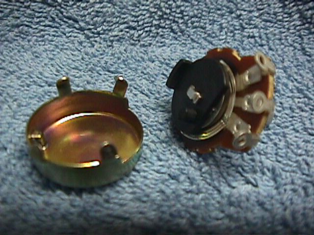
:For sure you have seen the innards of the common potentiometer with its meager deposited resistance circle being right on the phenolic / bakelite circle and a double bifurcated tensioned brass / phospor bronze rotor, with its fingers pressing onto the resistive element.
:
:
:
:
:
:
:
:
:
:HOWEVER . . . on that Allen Bradley unit, expect a molded bisque ceramic body construction, with a central wide furrow being molded within, that being for the THICK resistance element to be deposited down within, then the unit being fired to bring that resistive slurry to a diamond hardened shiny glaze.
:
:
:Then, as for the rotor construction, expect it to be a miniaturized version of what you typicallly can see as the rubbing block contact that you would see riding around the bared end windings of a Variac transformer, quite an impressive rotor assembly. This beefing up of the unit will have the unit additionally taking on what I believe was a 2 watt rating.
:
:
:Seems like the bulk of the body colorization was being a reddish brown.
:
:
:
: . . . . . Allen Bradley type " J " potentiometer
:
:
:
:
:Now IRC also made an equivalent unit, which had a greenish appearance for the body color.
:
:
:Possibly you could find one of either of those units, as surplus, to be used.
:
:
:OR . . . . I do believe that DigiKey and Mouser are offering current day "knock off versions" from over the waters manufacturers.
:
:
:Thassit . . .
:
:
:
:73's de Edd
:
:
:
:
:
:
:
:
:
:
:
:
:
:::Hi Edd,
::
::Thanks for keeping me straight.
::
::The hum problem was poor grounding of the shielded cable around the input to the volume control.
::
::I'll look for a 10K pot. The original is not wire wound. The carbon track has a 1/8" crack in it.
::
::I agree about the knobs, the whole unit is pretty unattractive. Luckily, it's not my radio. I like my Hallicrafters.
::
::Thanks again Edd.
::
::Bud.
::
::
::
::
:::
:::
:::
:::
:::
:::
:::
:::
:::
:::
:::
:::
:::Sir Bud Rrrruhhhh . . . . .
:::
:::
:::
:::
:::Grounding the 12A6 grid killed the hum so I guess that tube is faulty even though it tested fine. I'll have to order another. . . . . . (not yet . . not yet ! ).
:::
:::
:::
:::Au contraire . . . that is a good sign . . . as it is indicating that the hum is NOT coming from the B+ supply feeding that tubes plate supply nor its B+ screen grid feed, but of origin BEFORE the 12A6 and then being amplified.
:::
:::
:::
:::Soooooo . . . we just need to move back one earlier stage and ground the 1st grid of the 1st AF triode of the 12AV6, and see what that then tells us.
:::
:::
:::
:::I think that all you need to do now is to move back to the IF stage and get a 10 K pot to put in that RF gain position.
:::
:::
:::( Unless you are familiar with the housing and brand, additionally pull the back metal cover of the old pot and see if it just might have been a wire wound unit, after having computed the power being consumed in that loop.)
:::
:::
:::With heavy rotational use, they are also more prone to snagging with the rotor and opening in that manner.
:::
:::
:::Put a metal film resistor in place of the 12K 2W unit, as they are also made in 3 and 7 watt ratings. I really like them, as I have seen them used commercially in new transmitting electronics where they could be see to take on a dull red coloration from heat, if viewed in a dark room.
:::
:::
:::Stable as can be, also.
:::
:::
:::
:::Aside:
:::
:::
:::Using the words of Red Skeltons . . . Junior . . . ( 'de mean widdle kid ) . . . a la 30-40-50's night time radio:
:::
:::
:::'dat jus don't look right to me . . . . . . . . NO 'DAT JUS DON'T LOOK WIGHT TO ME !
:::
:::
:::
:::
:::And of course I am referring to the SMALL DakWare pointer knobs strung across the bottom controls for that unit.
:::
:::
:::Particularly for the band switch . . . I might consider that gripping and rotational challenge, being akin to an attempt of my pulling the lug nuts on my Mercy-Days with a 3/8 inch socket set.
:::
:::
:::
:::
:::
:::73's de Edd
:::
:::
:::
:::
:::
:::
:::
:::
:::
:::
:::
:::
::::A current of 11ma in a 15k resistor will need to dissipate 1.8 watts.
::::
::::So a 2 watt resistor is cutting it kinda close.
::::
::::Conservative design would double or triple it for safety.
::::Try at least a 4 or 5 watt resistor.
::::
::::
:::
::
:
I had always had quite a few of those "J" pots in stock, but now see that I no longer have one in a 5 k value. The one factor of that type "J" control is its hermetically sealed aspect, and in not having to be paying for You might reference this catalog page and possibly select 'twixt the three offerings, in accordance to shafting, as all three are 2 watt units. Mouser supplied " 53 SERIES" OF HONEYWELL / CLAROSTAT potentiometers:
|
Thanks Edd, I was unaware of this type of pot, I will try to find one. I definitely was not going to put in a pot similar to the original. It would be interesting to know how long it lasted. Bud Sir Bud Rrrr. . . . . "Be all that you can be" . . . . or wouldn't an appropriate servicing related axiom variant of that be ?
GOOD showing . . . on your sleuthing so far . . .
::"Do the best that you can do"
::
::
::And of course I am referring to that pot and the power that it actually can be receiving in some positions, as your mehanical disassembly and an examination has revealed.
::
::
::If that was my situation, I would be replacing that unit with a 10K Allan Bradley type "J" potentiomenter.
::
::
::For sure you have seen the innards of the common potentiometer with its meager deposited resistance circle being right on the phenolic / bakelite circle and a double bifurcated tensioned brass / phospor bronze rotor, with its fingers pressing onto the resistive element.
::
::
::
::
::
::
::
::
::
::HOWEVER . . . on that Allen Bradley unit, expect a molded bisque ceramic body construction, with a central wide furrow being molded within, that being for the THICK resistance element to be deposited down within, then the unit being fired to bring that resistive slurry to a diamond hardened shiny glaze.
::
::
::Then, as for the rotor construction, expect it to be a miniaturized version of what you typicallly can see as the rubbing block contact that you would see riding around the bared end windings of a Variac transformer, quite an impressive rotor assembly. This beefing up of the unit will have the unit additionally taking on what I believe was a 2 watt rating.
::
::
::Seems like the bulk of the body colorization was being a reddish brown.
::
::
::
:: . . . . . Allen Bradley type " J " potentiometer
::
::
::
::
::Now IRC also made an equivalent unit, which had a greenish appearance for the body color.
::
::
::Possibly you could find one of either of those units, as surplus, to be used.
::
::
::OR . . . . I do believe that DigiKey and Mouser are offering current day "knock off versions" from over the waters manufacturers.
::
::
::Thassit . . .
::
::
::
::73's de Edd
::
::
::
::
::
::
::
::
::
::
::
::
::
::::Hi Edd,
:::
:::Thanks for keeping me straight.
:::
:::The hum problem was poor grounding of the shielded cable around the input to the volume control.
:::
:::I'll look for a 10K pot. The original is not wire wound. The carbon track has a 1/8" crack in it.
:::
:::I agree about the knobs, the whole unit is pretty unattractive. Luckily, it's not my radio. I like my Hallicrafters.
:::
:::Thanks again Edd.
:::
:::Bud.
:::
:::
:::
:::
::::
::::
::::
::::
::::
::::
::::
::::
::::
::::
::::
::::
::::Sir Bud Rrrruhhhh . . . . .
::::
::::
::::
::::
::::Grounding the 12A6 grid killed the hum so I guess that tube is faulty even though it tested fine. I'll have to order another. . . . . . (not yet . . not yet ! ).
::::
::::
::::
::::Au contraire . . . that is a good sign . . . as it is indicating that the hum is NOT coming from the B+ supply feeding that tubes plate supply nor its B+ screen grid feed, but of origin BEFORE the 12A6 and then being amplified.
::::
::::
::::
::::Soooooo . . . we just need to move back one earlier stage and ground the 1st grid of the 1st AF triode of the 12AV6, and see what that then tells us.
::::
::::
::::
::::I think that all you need to do now is to move back to the IF stage and get a 10 K pot to put in that RF gain position.
::::
::::
::::( Unless you are familiar with the housing and brand, additionally pull the back metal cover of the old pot and see if it just might have been a wire wound unit, after having computed the power being consumed in that loop.)
::::
::::
::::With heavy rotational use, they are also more prone to snagging with the rotor and opening in that manner.
::::
::::
::::Put a metal film resistor in place of the 12K 2W unit, as they are also made in 3 and 7 watt ratings. I really like them, as I have seen them used commercially in new transmitting electronics where they could be see to take on a dull red coloration from heat, if viewed in a dark room.
::::
::::
::::Stable as can be, also.
::::
::::
::::
::::Aside:
::::
::::
::::Using the words of Red Skeltons . . . Junior . . . ( 'de mean widdle kid ) . . . a la 30-40-50's night time radio:
::::
::::
::::'dat jus don't look right to me . . . . . . . . NO 'DAT JUS DON'T LOOK WIGHT TO ME !
::::
::::
::::
::::
::::And of course I am referring to the SMALL DakWare pointer knobs strung across the bottom controls for that unit.
::::
::::
::::Particularly for the band switch . . . I might consider that gripping and rotational challenge, being akin to an attempt of my pulling the lug nuts on my Mercy-Days with a 3/8 inch socket set.
::::
::::
::::
::::
::::
::::73's de Edd
::::
::::
::::
::::
::::
::::
::::
::::
::::
::::
::::
::::
:::::A current of 11ma in a 15k resistor will need to dissipate 1.8 watts.
:::::
:::::So a 2 watt resistor is cutting it kinda close.
:::::
:::::Conservative design would double or triple it for safety.
:::::Try at least a 4 or 5 watt resistor.
:::::
:::::
::::
:::
::
: