Here's a neat little sub miniature 4 tube ( 5902 dual-channel push pull) iPod amplifier project that you guys might be interested in building as I just did.
A month or two ago I started on this project with great hopes for a reasonably similar result as the one I'm attempting to duplicate.
I found the initial information here at RVR labs:
http://www.rvrlabs.net/page57/page57.html
The project was found at RVRLABS' Site and this is what I'm attempting to duplicate:

http://www.rvrlabs.net/page57/page57.html
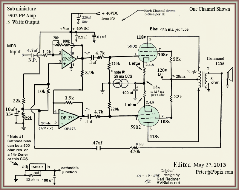
Here's the schematic that I'm following.
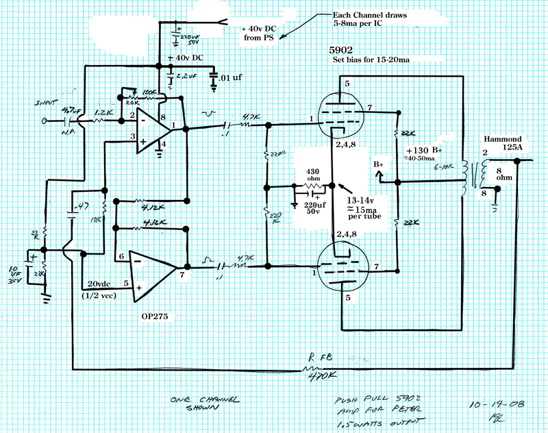
The only change that I made was to replace the individual cathode bias resistors and by-pass caps with a single common cathode bias resistor of 420 ohms.
I didn't know if I should be using a bypass cap in the cathode resistor here or not.
I thought Norm Leal indicated to me once that with a single common cathode resistor.... that by-pass caps aren't needed.
But I have decided to use a 220uf-50v by-pass cap anyway.
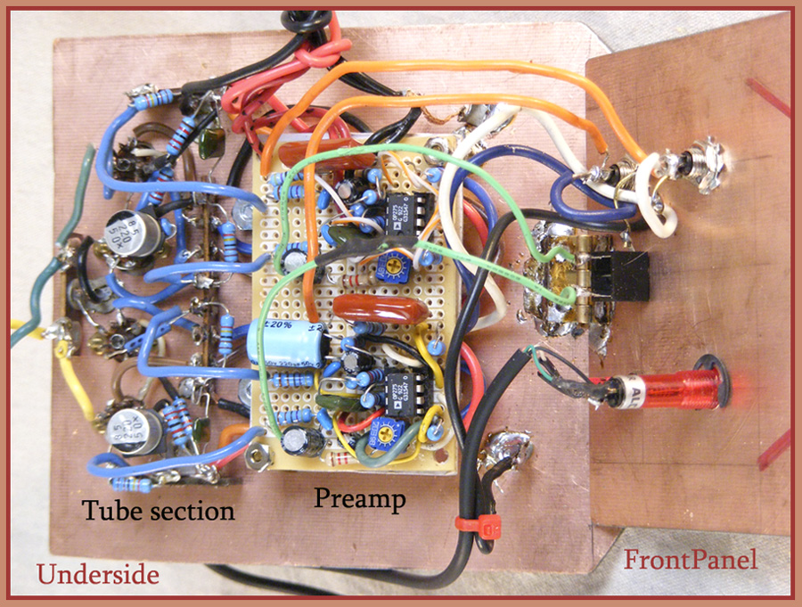
Here's my assembly of BOTH preamp channels on a single tiny 3"x2" perf board from Radio-Shack.
I'm not used to working so small since we usually are digging around these 1940s radios where EVERY-thing is ginormous comparatively speaking.
So I simply put on an extra pair of eye-glasses and cranked my solder iron temp back a bit and came up with this little crowded circuit.
I know it seems like there's a lot more stuff on there than the schematic indicates... but I now believe that the schematic was just meant to "trap" you into thinking it's a simple little project!...lol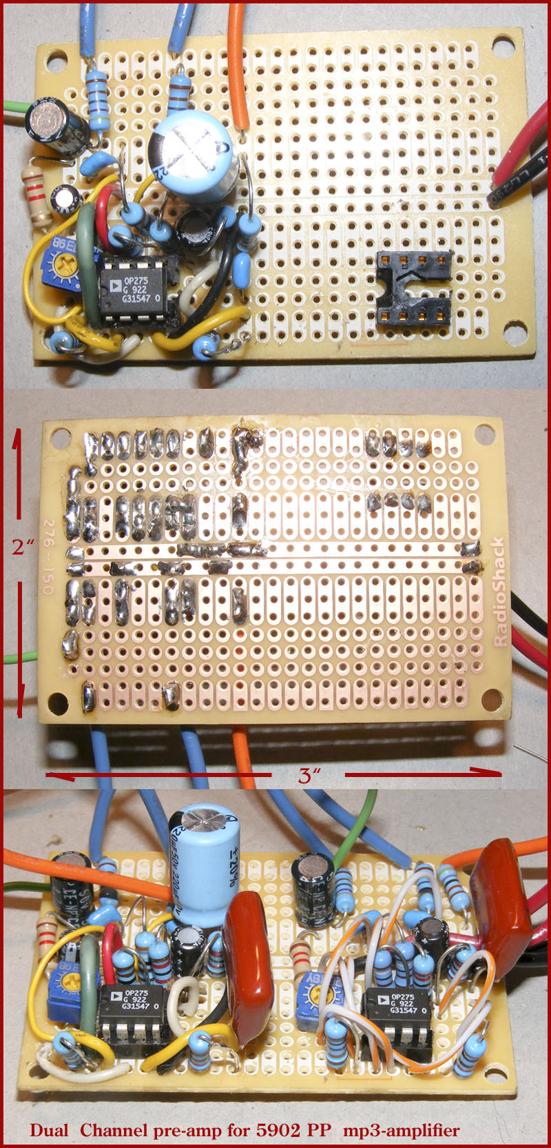
The project, as shown at RVR Labs, did not include a power supply.
So after researching some similar project supply circuits I came up with the following schematic with a lot of my own ideas added to it: 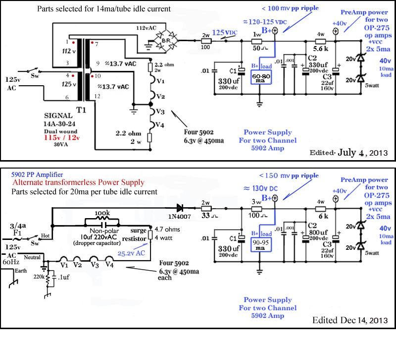
So then... I ordered up some copper-clad PC board and cut it to the size I needed for the box of my choice that I'd be using to house the amp.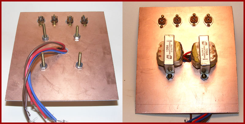
I was able to cut the board with a hacksaw with relative ease.
I had a devil of a time finding some sub-miniature tube sockets and finally found 6 or 8 of them at some remote place on-line and had to pay over $4 per socket plus shipping!
The 5902 tubes themselves, ( also quite scarce) were supplied to me by a very kind fellow at ARF for shipping costs.
Drilling the holes for the sockets was a bit tough for me. I bought the largest drill bit that would fit in my drill chuck.
However my chuck doesn't hold very well so it kept coming loose.
Then I still had to ream out each hole a bit afterward for the correct fit. I needed #2/56 screws to hold 'em in place so that meant 8 more tiny holes to drill.
Boy do I wish I had a nice drill press...lol
I decided to run all of the output transformer wires through one common center hole. That meant mounting them slightly above the board with a nut as a spacer and then I routed the primary wires under the transformers.
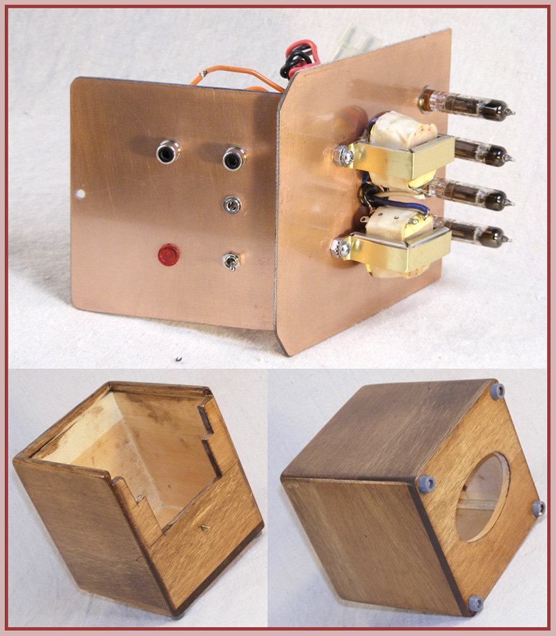
Quite luckily, I found a pretty good box at the craft store for only $1.
It seemed great to simply turn it over and remove the bottom panel and instead I could slide in MY copper board.
That puts the oval tissue-box hole on the bottom making for a great exit-way for wires and airflow. 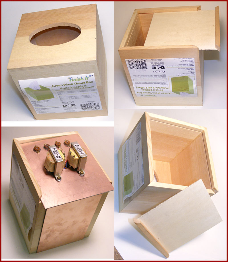

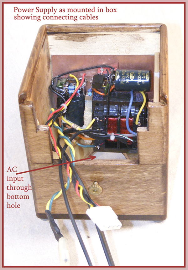
Note: I completely changed the power supply from the one pictured here in the box. In a later picture below you will see the completely finished power supply.
I will be mounting the power switch and audio in/out jacks on another small copper panel on the front-side of the box.
The hardware will not mount properly through the thicker wood so I decided to cut away part of the wood front wall and I will mount another smaller copper panel from a hinge on the main board that will hang from a hinge flat down against and be attached to the front wall with access to it from the cut away wood section behind it.
I also stained the wood box with some Minwax Special Walnut penetrating stain. It will later receive a nice top coat of gloss lacquer.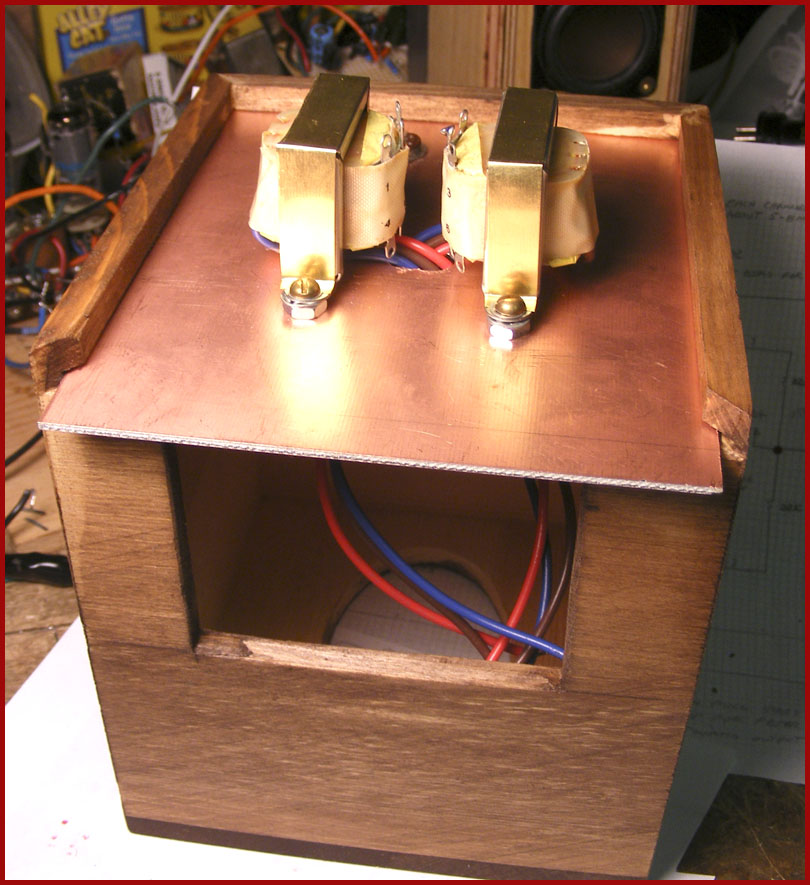
After mounting the tube sockets and building the preamp board it was time to wire and assemble the tube amplifier components to the socket pins.
This was another carefully thought out process as there was little room for error.... especially since I don't have but a few more of these little sockets and I wanted to make everything layout as efficiently as possible and keep lead lengths nice and short as well.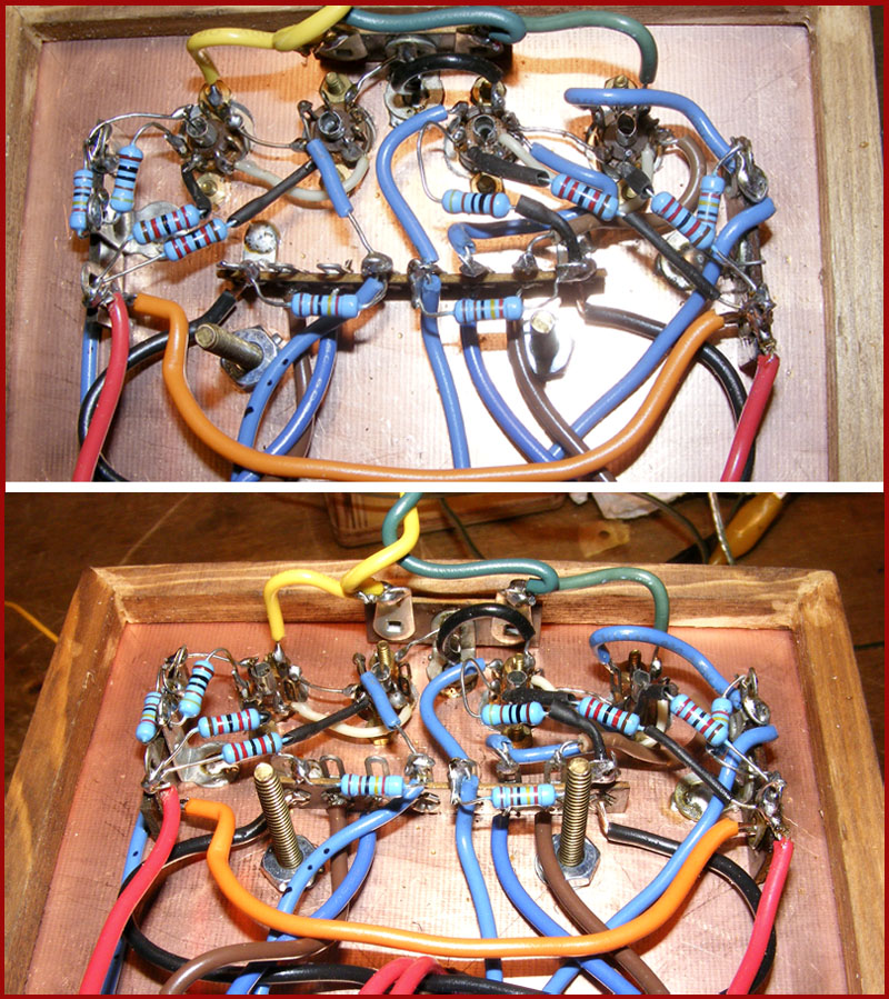
The Hammond transformers are "ok" but for $30 each I was hoping to get a better performer.
In my bread-board test circuit I used a different output transformer however.
It was a 1 amp dual-wound Tamura 6.3v/115 transformer ( 3FD-412).
I used it as a PP output transformer which performed (to my ear) much better that the Hammond 125A.
I used the two 115v windings in series (230 ct ) and the junction as the CT for B+ input.
Then I paralleled the two 6.3-volt windings for the speaker side.
Remember... to calculate the proper winding ratio.... the 6.3-volt winding actually produces 7.2 volts un-loaded.. right?
( I actually tested the turns ratio of this transformer by putting a 400hz signal in on the 230v side @ 1v rms and measured .0319volts out on the 6.3 volt side. 1/.0319 = 32. Conversely I put .072v rms in the 6.3v side and measured 2.3v rms on the 230v winding side. And calculating that we get 2.3/.072=32 )
[You can measure the ratio with 60hz as well. Just feed in 10 volts in on the primary and then measure the secondary... then divide to get the ratio.]
Anyway... I'm wiring the the two 115 volt windings in series to get 230.. right?
So 230/7.2 = 32 :1 turns ratio.
Since the primary impedance is equal to the square of the turns ratio times the speaker impedance.
So we have a 32:1 turns ratio.
32 squared = 1024
.... and if we use an 8 ohm speaker then 8 x 1024 = 8,192 ohms
This is just about right for these tubes.
When using the Hammond 125A I used taps 2 and 5 giving what seems like the best performance for it with about 8,200 ohms according to the Hammond tap table for an 8 ohm speaker.
Okay..
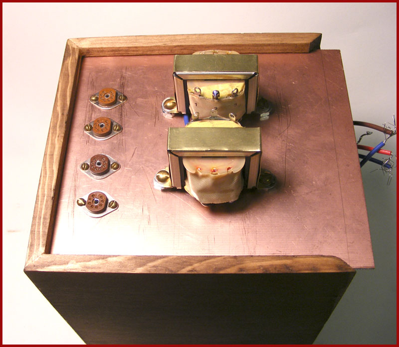
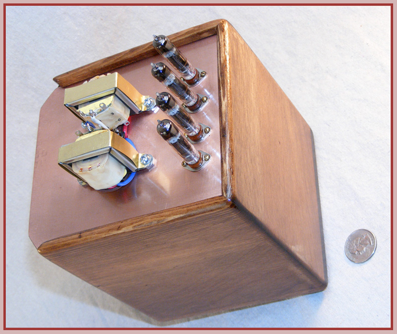
So, I installed the output transformers and inserted the tubes and fired it up. I didn't like the writing on the top of the Hammond transformers so I cut out some thin shiny brass covers for them to dress it up a little.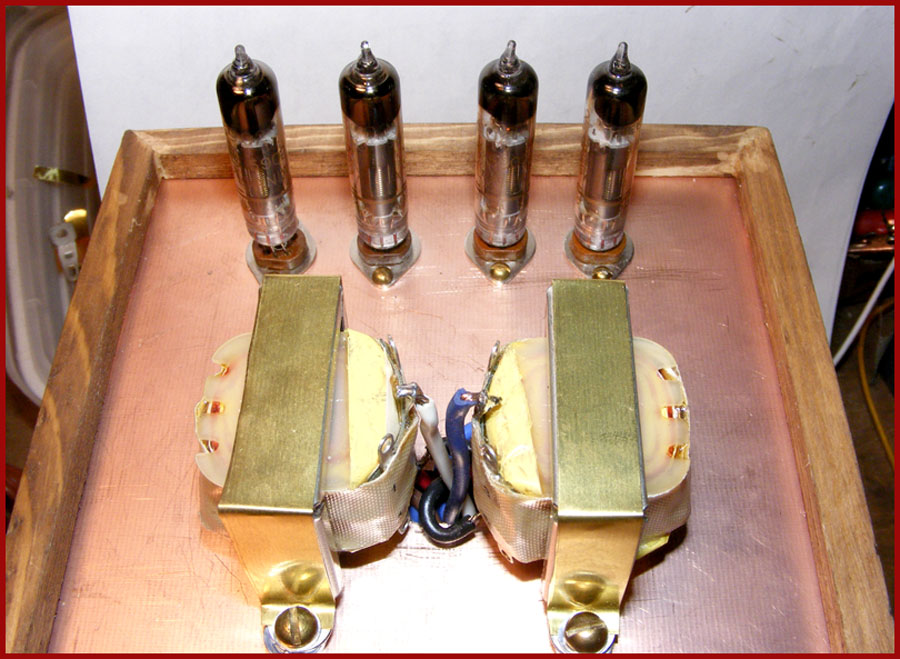
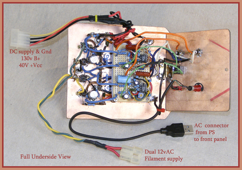
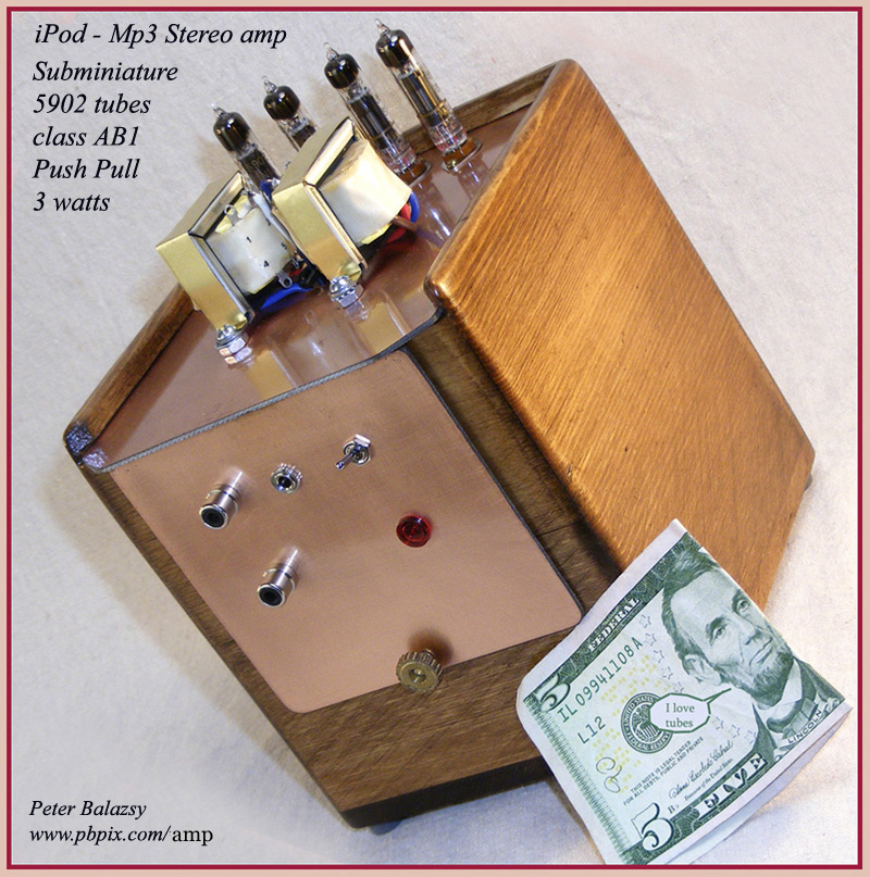
Ok so now I've completed the project:
Here is the final layout and completed amplifier.
The entire amp, power supply, pre-amp/tube assembly and the wooden box housing .... are all FINALLY assembled and working!!
The power supply fits nicely inside the box against the back wall below the tube area and it runs nicely without any heat build up.
I am very pleased with the results.
To my ear... the amp sounds fantastic too!
Here it is.
I'll show pictures showing the power supply and other views a little further down the page: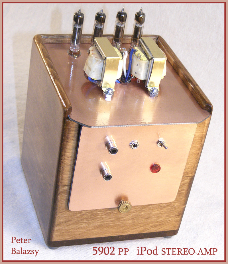
Now...
Here's the power supply and some other pictures of how the whole thing fits together.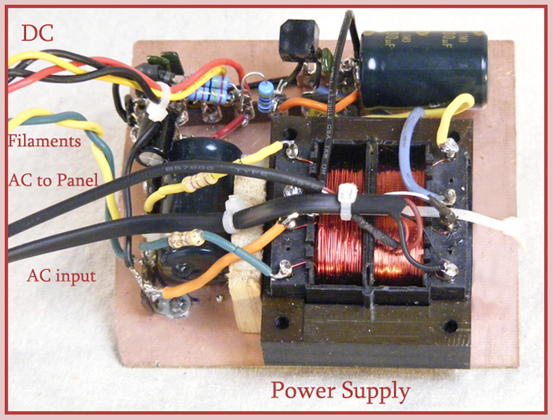
I heartily recommend this project to all you iPod lovers and tube-amp lovers!
... (even if you decided to use 6ak6 tubes that draw less filament juice and easier to find)
.... It has been lots of fun and thoroughly rewarding.
It was my very first ever amplifier build... and I had a lot of fun doing this.
Go for it! It's a lot of fun.
Here is where you can find info on the OP-275 jfet opamps I used.
http://www.analog.com/static/imported-files/data_sheets/OP275.pdf
I designed the power supply myself with some greatful input from others at ARF.
ALL the credit and my grateful thanks.. for the design of the amplifier section itself is to [b]Mr. Karl Redmer[/b] of RVRLabs:
at http://www.rvrlabs.net/page57/page57.html
T.
Richard
:Looks good! I love to build things like that. For now I'm busy with other stuff, but I'd really like to build an AC/DC radio, possibly with FM, inside of this small covered wooden box I picked up a few years ago. It'd be a fun project, especially for kids. I may build it and then tear it down for some nephews of mine to build.
T.
:
:
http://www.analog.com/static/imported-files/data_sheets/OP275.pdf
::An Op-Amp? What kind of atrocity is this? Don't you know the balance of the universe will be upset? You have mixed tubes and silicon. Shame, shame, shame. The electron gods will get you.
::
::
:
:I only personally designed the power supply part of this project so I can not speak to the device selection reasoning of the op275 op-amp at the amplifier design time.
:
:It does sound truly wonderful.. however.
:
:I built and used the amp schematic basically "as is".
:
: It was designed by Karl Redmer of RVRlabs: http://www.rvrlabs.net/page57/page57.html
:
:The OP275 gets great respect from the tube-amp audiophile community.
:
:Here's the data sheet:
:http://www.analog.com/static/imported-files/data_sheets/OP275.pdf
:
And this one seemed relatively easily build-able...and the Jfet op-amps are something I wanted to experience the sound with too.
So that's what intrigued me and got me started.
like anything else hobby-wise you never know where it will take you.
Like this one. lol
Back in 2005 I just wanted to fix ONE old radio that I found while cleaning my garage!
Here it is 4 years later and a garage full of radios now!.
... and old radios and radio-crap has become a way of life. See? It gets to ya.