:
I have seen this loose wire on other Zenith models too. Usually it is just half wrapped, but not connected to, the other lead going to the grid cap of the mixer/detector tube. I think this loose wire is a pigtail lead that is used in some models, but not others.
::
:I have seen this loose wire on other Zenith models too. Usually it is just half wrapped, but not connected to, the other lead going to the grid cap of the mixer/detector tube. I think this loose wire is a pigtail lead that is used in some models, but not others.
:
:::
::I have seen this loose wire on other Zenith models too. Usually it is just half wrapped, but not connected to, the other lead going to the grid cap of the mixer/detector tube. I think this loose wire is a pigtail lead that is used in some models, but not others.
::
:
:OK then maybe I am not crazy. I Googled images of Zenith chassis and it appears the one wire was looped once around the other.
:
:http://wd4eui.com/Pictures/Antique_Radios/Zenith5S218_chassis_top.jpg
:
:Do you think I should just do the same? It is a little short to reach the other wire, I would have to replace it.
:
No, I don't think its necessary. It is not critical.
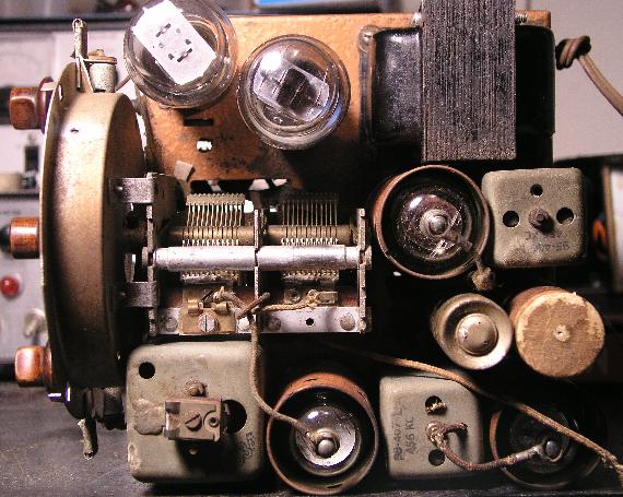
::::The tuning capacitor thingy, has two wires on top. One goes to the top of the adjoining tube, the other wire is just hanging. Is it supposed to do that?
::::
:::I have seen this loose wire on other Zenith models too. Usually it is just half wrapped, but not connected to, the other lead going to the grid cap of the mixer/detector tube. I think this loose wire is a pigtail lead that is used in some models, but not others.
:
:
:::
::
::OK then maybe I am not crazy. I Googled images of Zenith chassis and it appears the one wire was looped once around the other.
::
::http://wd4eui.com/Pictures/Antique_Radios/Zenith5S218_chassis_top.jpg
::
::Do you think I should just do the same? It is a little short to reach the other wire, I would have to replace it.
::
:
:No, I don't think its necessary. It is not critical.
:

Sirs . . . .
That wire is there for the option of injecting more local oscillator RF level into the mixer secton. Sometimes beneficial in getting better operation at the high end of the SW spectrum.
The illustration below , should it have been present on your schema , clearly shows the maximum option of having multiple turns of insulated hook up wire wound around a second wire. Commonly being referred to as a "gimmick capacitor."
A tight coiling action could create multiple pf's of capacitance between the two wire elements, whereas, a single half loop around the companion wire might only create a few pf or so of intercoupling capacitance.

Its degree of required / created compensatory capacitance, if any, would typically be ascertained by the alignment of a unit during factory final test.
73's de Edd

:
:
:
:
:
:Sirs . . . .
:
:
:
:
:
:That wire is there for the option of injecting more local oscillator RF level into the mixer secton. Sometimes beneficial in getting better operation at the high end of the SW spectrum.
:
:
:The illustration below , should it have been present on your schema , clearly shows the maximum option of having multiple turns of insulated hook up wire wound around a second wire. Commonly being referred to as a "gimmick capacitor."
:
:A tight coiling action could create multiple pf's of capacitance between the two wire elements, whereas, a single half loop around the companion wire might only create a few pf or so of intercoupling capacitance.
:
:
:
:
:
:
:
:
:
:Its degree of required / created compensatory capacitance, if any, would typically be ascertained by the alignment of a unit during factory final test.
:
:
:
:
:
:
:
But Edd...This wire has a lug on it and it's just dangling there like it's just dying to be hooked to the tuning condenser...I don't think it's on the schema...Are you saying that Zenith would let a wire with a lug just dangle there?...Neal
:73's de Edd
:
:
:
:
:
:
::
::
::
::
::
::Sirs . . . .
::
::
::
::
::
::That wire is there for the option of injecting more local oscillator RF level into the mixer secton. Sometimes beneficial in getting better operation at the high end of the SW spectrum.
::
::
::The illustration below , should it have been present on your schema , clearly shows the maximum option of having multiple turns of insulated hook up wire wound around a second wire. Commonly being referred to as a "gimmick capacitor."
::
::A tight coiling action could create multiple pf's of capacitance between the two wire elements, whereas, a single half loop around the companion wire might only create a few pf or so of intercoupling capacitance.
::
::
::
::
::
::
::
::
::
::Its degree of required / created compensatory capacitance, if any, would typically be ascertained by the alignment of a unit during factory final test.
::
::
::
::
::
::
::
:But Edd...This wire has a lug on it and it's just dangling there like it's just dying to be hooked to the tuning condenser...I don't think it's on the schema...Are you saying that Zenith would let a wire with a lug just dangle there?...Neal
:
The wire of which I speak is associated with the top of the tuning condenser, the front portion of the tuning condenser is the ANT section and the rear is the local oscillator. It is readily apparent that the front section terminal "lug" is connecting to the plate cap of the mixer. The mystery wire and its connection to ITS "lug" is having that "lug" being connected to the topside half of the oscillator's fixed position stator section . But the main oscillator circuitry connections to the osc stator are down on the OTHER lug at the botom section of the stator near the chassis pans proximity.
The selection of the placement of the additional lug at the top side of the tuning condenser made it quite convenient to quickly reach over to the mixer antenna grid, as opposed to routing from below chassis and all of the addditional radiation and stray capacitance involved in that long of a run from bottom chassis.
73's de Edd
:::
:::
:::
:::
:::
:::Sirs . . . .
:::
:::
:::
:::
:::
:::That wire is there for the option of injecting more local oscillator RF level into the mixer secton. Sometimes beneficial in getting better operation at the high end of the SW spectrum.
:::
:::
:::The illustration below , should it have been present on your schema , clearly shows the maximum option of having multiple turns of insulated hook up wire wound around a second wire. Commonly being referred to as a "gimmick capacitor."
:::
:::A tight coiling action could create multiple pf's of capacitance between the two wire elements, whereas, a single half loop around the companion wire might only create a few pf or so of intercoupling capacitance.
:::
:::
:::
:::
:::
:::
:::
:::
:::
:::Its degree of required / created compensatory capacitance, if any, would typically be ascertained by the alignment of a unit during factory final test.
:::
:::
:::
:::
:::
:::
:::
::But Edd...This wire has a lug on it and it's just dangling there like it's just dying to be hooked to the tuning condenser...I don't think it's on the schema...Are you saying that Zenith would let a wire with a lug just dangle there?...Neal
::
:
:
:
:The wire of which I speak is associated with the top of the tuning condenser, the front portion of the tuning condenser is the ANT section and the rear is the local oscillator. It is readily apparent that the front section terminal "lug" is connecting to the [ GRID] cap of the mixer. The mystery wire and its connection to ITS "lug" is having that "lug" being connected to the topside half of the oscillator's fixed position stator section . But the main oscillator circuitry connections to the osc stator are down on the OTHER lug at the botom section of the stator near the chassis pans proximity.
:
:
:The selection of the placement of the additional lug at the top side of the tuning condenser made it quite convenient to quickly reach over to the mixer antenna grid, as opposed to routing from below chassis and all of the addditional radiation and stray capacitance involved in that long of a run from bottom chassis.
:
:
:
:
:
:
:
:
:
:
:
:73's de Edd
:
:
:
:
:
:
:
::::
::::
::::
::::
::::
::::
::::Sirs . . . .
::::
::::
::::
::::
::::
::::That wire is there for the option of injecting more local oscillator RF level into the mixer secton. Sometimes beneficial in getting better operation at the high end of the SW spectrum.
::::
::::
::::The illustration below , should it have been present on your schema , clearly shows the maximum option of having multiple turns of insulated hook up wire wound around a second wire. Commonly being referred to as a "gimmick capacitor."
::::
::::A tight coiling action could create multiple pf's of capacitance between the two wire elements, whereas, a single half loop around the companion wire might only create a few pf or so of intercoupling capacitance.
::::
::::
::::
::::
::::
::::
::::
::::
::::
::::Its degree of required / created compensatory capacitance, if any, would typically be ascertained by the alignment of a unit during factory final test.
::::
::::
::::
::::
::::
::::
::::
:::But Edd...This wire has a lug on it and it's just dangling there like it's just dying to be hooked to the tuning condenser...I don't think it's on the schema...Are you saying that Zenith would let a wire with a lug just dangle there?...Neal
:::
::
::
::
::The wire of which I speak is associated with the top of the tuning condenser, the front portion of the tuning condenser is the ANT section and the rear is the local oscillator. It is readily apparent that the front section terminal "lug" is connecting to the [ GRID] cap of the mixer. The mystery wire and its connection to ITS "lug" is having that "lug" being connected to the topside half of the oscillator's fixed position stator section . But the main oscillator circuitry connections to the osc stator are down on the OTHER lug at the botom section of the stator near the chassis pans proximity.
::
::
::The selection of the placement of the additional lug at the top side of the tuning condenser made it quite convenient to quickly reach over to the mixer antenna grid, as opposed to routing from below chassis and all of the addditional radiation and stray capacitance involved in that long of a run from bottom chassis.
::
::
::
::
::
::
::
::
::
::
::
::73's de Edd
::
::
::
::
::
::
::
:
Nevermind...you have answered that question already...Neal
:
:
:::::
:::::
:::::
:::::
:::::
:::::
:::::Sirs . . . .
:::::
:::::
:::::
:::::
:::::
:::::That wire is there for the option of injecting more local oscillator RF level into the mixer secton. Sometimes beneficial in getting better operation at the high end of the SW spectrum.
:::::
:::::
:::::The illustration below , should it have been present on your schema , clearly shows the maximum option of having multiple turns of insulated hook up wire wound around a second wire. Commonly being referred to as a "gimmick capacitor."
:::::
:::::A tight coiling action could create multiple pf's of capacitance between the two wire elements, whereas, a single half loop around the companion wire might only create a few pf or so of intercoupling capacitance.
:::::
:::::
:::::
:::::
:::::
:::::
:::::
:::::
:::::
:::::Its degree of required / created compensatory capacitance, if any, would typically be ascertained by the alignment of a unit during factory final test.
:::::
:::::
:::::
:::::
:::::
:::::
:::::
::::But Edd...This wire has a lug on it and it's just dangling there like it's just dying to be hooked to the tuning condenser...I don't think it's on the schema...Are you saying that Zenith would let a wire with a lug just dangle there?...Neal
::::
:::
:::
:::
:::The wire of which I speak is associated with the top of the tuning condenser, the front portion of the tuning condenser is the ANT section and the rear is the local oscillator. It is readily apparent that the front section terminal "lug" is connecting to the [ GRID] cap of the mixer. The mystery wire and its connection to ITS "lug" is having that "lug" being connected to the topside half of the oscillator's fixed position stator section . But the main oscillator circuitry connections to the osc stator are down on the OTHER lug at the botom section of the stator near the chassis pans proximity.
:::
:::
:::The selection of the placement of the additional lug at the top side of the tuning condenser made it quite convenient to quickly reach over to the mixer antenna grid, as opposed to routing from below chassis and all of the addditional radiation and stray capacitance involved in that long of a run from bottom chassis.
:::
:::
:::
:::
:::
:::
:::
:::
:::
:::
:::
:::73's de Edd
:::
:::
:::
:::
:::
:::
:::
::
: