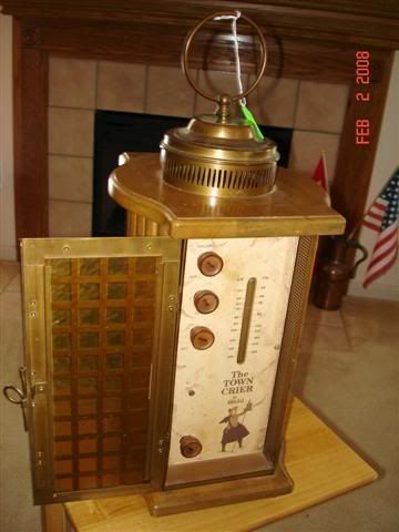
Anyone ??

:
:Anyone ??
:
:

Dennis: I think that's a model 380T, circa 1956. Apparently some have 7 tubes, and other versions had 8. Someone else on another forum was recently looking for schematics and found one on eBay. They made a number of interesting novelty radios including a spice chest, and antique telephone. Hope you find it.
Steve
It seems that the only schematic that ever existed is the one that came in the users booklet that was packed with each new radio. None of the usual schematic producers published any information on the radio....as far as I can determine...........
Have you tried placing a post in the ARF? Someone in there may have a copy. I can post a message inquiring about one if you'd like.
:Yes, I was one of the guys bidding on that eBay service info. Unfortunately I was outbid. I emailed the winner of the auction and offered to pay him for copying the schematic but I never received a reply.
:
:It seems that the only schematic that ever existed is the one that came in the users booklet that was packed with each new radio. None of the usual schematic producers published any information on the radio....as far as I can determine...........
Tyat particular schematic is about as rare as hen's teeth.

Don’t know if you have the unit on hand and it is a non operational unit, OR, if merely wanting a schematic back up for the future…..sooooo….. for all that its worth in the “any help” category, here is a capture and enhancement…within its source limitations….. of the original small sticker coming with a unit.
At least it pinpoints the tube placements and types, be it using a dual triode RF 12DT8 or its companion 17EW8 . A least the unit shows to be being used as a grounded grid RF amp and then its mixing function following afterwards. The 12BE6 used as the common AM mixer and the unit using two stacked IF stages thru a single RF stage at 455 Khz and the whole 2x IF amps and following limiter at the 10.7 Mhz category. Two 1N541 diodes used in the FM detector stage.
The only low value resistors that you might want to track down and log in would be the input current rush resistor before and then the series resistor after the top hat rectifier diode.
Don’t know Guilds preferred choice for that diode, but an 1N4007 should certainly over qualify.
Down in the filament string seem to be two, possibly one, series power resistor to balance out the series string along with some choke coil isolation of the RF sections filament.
Due to sizing, this does print out as 4 quadrants, but they can then be overlaid.
73's de Edd

Edd,
this is the way the schematic appears (portion shown below) when I tyry to view it & zoom or print it. Resolution appears to be very low...the image does not improve even if I up the resolution much higher - even at 300 dpi. Any ideas ?


Alas, no, that was the best that could be done with the small copy, either pasted inside a cabinet or inside the owners manual off the internet…E-bay I believe…and gone, gone, gone now.
I mentioned that it would only serve as a rough signal flow chart or tube position identifier.
The original was shot either too far from the page or deficient in pixel counts on the cameras mosaic…even a scanning would have done better.For all of the dithering, digital enhancement and sharpening, that was the best that could be acquired.
Here is what sizing that I was working with originally:
As mentioned, now might be the time to seek out and write down the low value resistors in the unit for future reference, as a scorched black-black-black or black black-brown doesn’t exactly decipher later on.
73's de Edd

ums/x133/Dennistheradioguy/TownCrierSchemProject.jpg>