I replaced some of the capacitors and noticed that the 80 tube had blue around the filaments and got really hot, so that tells me something is drawing too much current. I forgot to hookup the ground lead of the 004 cap off the 47, would this cause the 80 tube to overheat?
I was about to replace the 325 ohm resistor because I thought it was supposed to be 300mohms but there are 2 model r schematics. The one my radio matches is page 8-2, bottom schematic. "model r sereal 175001 and up. Yep it sure helps to be looking at the right schematic!!!
:Hello I am trying to replace the 2 filter caps that are marked 4 uf. I cant seem to determine what polarity the common wire between the two caps is supposed to be. My guess would be Neg since it goes to the filament string which is also the 80 tubes cathode. Am I right?
: I replaced some of the capacitors and noticed that the 80 tube had blue around the filaments and got really hot, so that tells me something is drawing too much current. I forgot to hookup the ground lead of the 004 cap off the 47, would this cause the 80 tube to overheat?
: I was about to replace the 325 ohm resistor because I thought it was supposed to be 300mohms but there are 2 model r schematics. The one my radio matches is page 8-2, bottom schematic. "model r sereal 175001 and up. Yep it sure helps to be looking at the right schematic!!!
Start with fresh electrolytics. It is possible that you ruined the ones you are using currently. They cannot be installed backwards.
T.
:The rectifier cathode is always the most positive part of the set. Both of the electrolytics' positives should go to the rectifier cathode. One negative should go on one side of the field coil, and the other goes to the other side of the field coil, as indicated in the schematic.
:
:Start with fresh electrolytics. It is possible that you ruined the ones you are using currently. They cannot be installed backwards.
:
:T.
::Ok translation, I should not stop working on radios so I wont forget how to replace caps. Ok I guess Im rusty at this but solid state diodes, isnt the cathode the negative and the anode positive?
::The rectifier cathode is always the most positive part of the set. Both of the electrolytics' positives should go to the rectifier cathode. One negative should go on one side of the field coil, and the other goes to the other side of the field coil, as indicated in the schematic.
::
::Start with fresh electrolytics. It is possible that you ruined the ones you are using currently. They cannot be installed backwards.
::
::T.
::Ok got the caps replaced and whatduya know it works again, thanks. Now one more question. I have a .1 uf cap on this thing I wanna replace, but it has a metal clip around it that goes most of the way around the body of the cap. The cap is the usuall axial lead type wax filled paper one. There is a wire soldered to this clip that goes to the 57 or 58 tube pin 4. I dont know what to do with this clip once I replace the cap since new caps are a lot smaller. Is this wire a feedback wire like in the philco model 80? I would guess it needs it but how do I keep this wire clip in use with a smaller cap size due to newer cap
:::Ok translation, I should not stop working on radios so I wont forget how to replace caps. Ok I guess Im rusty at this but solid state diodes, isnt the cathode the negative and the anode positive?
:::The rectifier cathode is always the most positive part of the set. Both of the electrolytics' positives should go to the rectifier cathode. One negative should go on one side of the field coil, and the other goes to the other side of the field coil, as indicated in the schematic.
:::
:::Start with fresh electrolytics. It is possible that you ruined the ones you are using currently. They cannot be installed backwards.
:::
:::T.
::OK update, the cap with the clip all the way around it is a .1 uf. It is connected from pin 3 (g2) to chassis ground. The wire that is soldered to the clip around the outside of the cap goes to pin 4 of the 58 tube. Do I just wrap the wire around the new .1 up cap, or is this kinda important to get it exactly hooked up like the original?
:::Ok got the caps replaced and whatduya know it works again, thanks. Now one more question. I have a .1 uf cap on this thing I wanna replace, but it has a metal clip around it that goes most of the way around the body of the cap. The cap is the usuall axial lead type wax filled paper one. There is a wire soldered to this clip that goes to the 57 or 58 tube pin 4. I dont know what to do with this clip once I replace the cap since new caps are a lot smaller. Is this wire a feedback wire like in the philco model 80? I would guess it needs it but how do I keep this wire clip in use with a smaller cap size due to newer cap
::::Ok translation, I should not stop working on radios so I wont forget how to replace caps. Ok I guess Im rusty at this but solid state diodes, isnt the cathode the negative and the anode positive?
::::The rectifier cathode is always the most positive part of the set. Both of the electrolytics' positives should go to the rectifier cathode. One negative should go on one side of the field coil, and the other goes to the other side of the field coil, as indicated in the schematic.
::::
::::Start with fresh electrolytics. It is possible that you ruined the ones you are using currently. They cannot be installed backwards.
::::
::::T.
I was just reading thru your problem with the old cap. One of the things I find with my old RCA victrola 612V3 is that there is unusual things done long ago that have long since disolved into the ether. I have also found, try it without, because most of these circuits aren't that critical. Sounds like some type filtering aftermarket fix by the manufacturer. Your guess is sound grasshopper.
Regards
Steve

I saw you hanging….stymied…. there also :
<" Ok I guess Im rusty at this but solid state diodes, isnt the cathode the negative and the anode positive?
">
On the typical solid state diode, the band / ring / dot referenced lead is the CATHODE and it would be the source of your + DC voltage if fed with raw AC into its other ANODE lead. 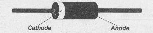
I’m looking at the two schematics on the page….. and you said that the top one was your "R" series unit… I do see the handling of the G2 ad G3 circuitry of the “Simple” little receiver and with nothing varying from the norm in the bypassing / decoupling actions of those .1ufd units.
Some manufacturers larger sized capacitors did sometimes have mounting straps around them, particularly, if used in a mobile environment like the military, where their mass , if left floating could result in vibrationally broken leads. I assume that they had the strap grounded with a screw or rivet and possibly the lead that would have went to ground…was soldered to that strap ?
The only other application special to a cap of that mechanical dimensions that I can remember is where there is a coil wound around a portion of the outside of the cap with several turns of wire, and then connected to one end of the cap with the other end of the coil wire going to ground.
That just mentioned cap is usually in the order of decimal 001ufd and the series inductor made with the wire results in a series L/C trap coil that shunts potentially bothersome low frequency signals from NAVTEK, GWEN and NAVBEACON transmissions .
I don’t think that you have that situation on your chassis, with a series RF attenuation trap built as I mentioned.
As well, your low mechanical mass replacement caps definitely should not need mechanical support.
73's de Edd
:Sean,
:I was just reading thru your problem with the old cap. One of the things I find with my old RCA victrola 612V3 is that there is unusual things done long ago that have long since disolved into the ether. I have also found, try it without, because most of these circuits aren't that critical. Sounds like some type filtering aftermarket fix by the manufacturer. Your guess is sound grasshopper.
:Regards
:Steve
:
:
:
:
:
:I saw you hanging….stymied…. there also :
:
:
:
:<" Ok I guess Im rusty at this but solid state diodes, isnt the cathode the negative and the anode positive?
:">
:
:
:On the typical solid state diode, the band / ring / dot referenced lead is the CATHODE and it would be the source of your + DC voltage if fed with raw AC into its other ANODE lead.
:
:
:
:
:
:
:
:I’m looking at the two schematics on the page….. and you said that the top one was your "R" series unit… I do see the handling of the G2 ad G3 circuitry of the “Simple” little receiver and with nothing varying from the norm in the bypassing / decoupling actions of those .1ufd units.
:
: Some manufacturers larger sized capacitors did sometimes have mounting straps around them, particularly, if used in a mobile environment like the military, where their mass , if left floating could result in vibrationally broken leads. I assume that they had the strap grounded with a screw or rivet and possibly the lead that would have went to ground…was soldered to that strap ?
:The only other application special to a cap of that mechanical dimensions that I can remember is where there is a coil wound around a portion of the outside of the cap with several turns of wire, and then connected to one end of the cap with the other end of the coil wire going to ground.
:That just mentioned cap is usually in the order of decimal 001ufd and the series inductor made with the wire results in a series L/C trap coil that shunts potentially bothersome low frequency signals from NAVTEK, GWEN and NAVBEACON transmissions .
:
:I don’t think that you have that situation on your chassis, with a series RF attenuation trap built as I mentioned.
:As well, your low mechanical mass replacement caps definitely should not need mechanical support.
:
:
:
:73's de Edd
:
:
:
:
:
:
:
:
:
:
:
::Sean,
::I was just reading thru your problem with the old cap. One of the things I find with my old RCA victrola 612V3 is that there is unusual things done long ago that have long since disolved into the ether. I have also found, try it without, because most of these circuits aren't that critical. Sounds like some type filtering aftermarket fix by the manufacturer. Your guess is sound grasshopper.
::Regards
::Steve
Good thing I've never done that.
Oh well
Steve
Hmmmm....I'm getting tired, and I'm not quite sure where I"m going anymore. Hope this helps.
T.
::Ok translation, I should not stop working on radios so I wont forget how to replace caps. Ok I guess Im rusty at this but solid state diodes, isnt the cathode the negative and the anode positive?
::The rectifier cathode is always the most positive part of the set. Both of the electrolytics' positives should go to the rectifier cathode. One negative should go on one side of the field coil, and the other goes to the other side of the field coil, as indicated in the schematic.
::
::Start with fresh electrolytics. It is possible that you ruined the ones you are using currently. They cannot be installed backwards.
::
::T.