This is my second attempt to get this set working. I bought a different model 60 chassis (minus the varaible tuning condensor which I had from my old set) and started the "philco blocks" rebuild as well as replacing any drifted resistors. The worst one I found today was supposed to be a 10,000 ohm and it was reading 320meg. Wow!
The oscillator tube that I had was dead, so I got a replacement.
Here are the readings:
Filamants should be 6.3VAC - I got 6.5VAC
P to K should be 250VDC - I got zero volts
Screen grid (SG to K) should be 85 VDC - I got minus 1.7VDC
Control grid (CG to K)- this is the tube cap - should be .18VDC - I got minus 1.9VDC
Cathode (K to F) should be 3.0 VDC - I got -85VDC
G1 to K should be 1.4VDc - I got 1.9VDC
G2 to K should be 180 VDC - I got 374VDC
The tone control "clicks" when I move it from position to position, so I haven't moved to the audio section at this time.
Touching the tube caps doesn't make any sound at all.
No BC or SW reception.
I am sure I am not the first one to have a Philco 60 problem, but I really want to get this baby working, else I would have trashed it or sold it for parts/
Ideas?
Thanks in advance for all of your help.
Terry F

The glaring thing is the lack of B+ on the plate , ( Plus your ultra squirrely G2 to cathode voltage !) Plus, you might have ended up with the the tubes cathode floating with your osc coilchangeout, etc. BUT the neg voltages tend to suggest the presence / continuity of the resistor sections of #47, but that would be a place to start….. with no power on the set…. confirm the continuity of its two sections by ohmming out from chassis geround to the top side that connects to the center tap of the power transformer. Designated as points A to B . If that confirmed as being intact, power up the set and start at the plate again with metering instrumentation then set to DC volts, chassis ground DC referencing, and re verify….if still no B+... a la plate 6A7, then you could drop right on down to the source of the B+ at test reference point L and work your way back towards test point C and if all of the wiring and interconnects are all correct and present to that point, looks like that 1st IF transformer plate winding / wiring needs some investigating. 
73's de Edd
:Dear All,
:
:This is my second attempt to get this set working. I bought a different model 60 chassis (minus the varaible tuning condensor which I had from my old set) and started the "philco blocks" rebuild as well as replacing any drifted resistors. The worst one I found today was supposed to be a 10,000 ohm and it was reading 320meg. Wow!
:
:The oscillator tube that I had was dead, so I got a replacement.
:
:Here are the readings:
:Filamants should be 6.3VAC - I got 6.5VAC
:P to K should be 250VDC - I got zero volts
:Screen grid (SG to K) should be 85 VDC - I got minus 1.7VDC
:Control grid (CG to K)- this is the tube cap - should be .18VDC - I got minus 1.9VDC
:Cathode (K to F) should be 3.0 VDC - I got -85VDC
:G1 to K should be 1.4VDc - I got 1.9VDC
:G2 to K should be 180 VDC - I got 374VDC
:
:The tone control "clicks" when I move it from position to position, so I haven't moved to the audio section at this time.
:
:Touching the tube caps doesn't make any sound at all.
:
:No BC or SW reception.
:
:I am sure I am not the first one to have a Philco 60 problem, but I really want to get this baby working, else I would have trashed it or sold it for parts/
:
:Ideas?
:
:Thanks in advance for all of your help.
:
:Terry F
:
I traced the B+ voltage as about 345VDC all the way bck to point "C". Then I lose it.
As stated before this wasn't my original chassis and now I see that there are two .09 mfd caps connected from the metal condensor can to the G1 and another to the G3/G5 pins of the 6A7 oscillator. I thought there was only supposed to be one to G3.
Is this correct?
That sketch you sent me was the best! I learned a lot from it.
Terry F
:Edd,
:
:I traced the B+ voltage as about 345VDC all the way bck to point "C". Then I lose it.
:
:As stated before this wasn't my original chassis and now I see that there are two .09 mfd caps connected from the metal condensor can to the G1 and another to the G3/G5 pins of the 6A7 oscillator. I thought there was only supposed to be one to G3.
:
:Is this correct?
:
:That sketch you sent me was the best! I learned a lot from it.
:
:Terry F
No b+ at "C". This is where I noticed the two condensor connections to the 6A7.
I have b+ up to point "D".
Terry
:Carlos,
:
:No b+ at "C". This is where I noticed the two condensor connections to the 6A7.
:
:I have b+ up to point "D".
:
:Terry
O.K.......I see ....since you found hi level sub B+ voltage intact upwards and being A L L L L the way thru to test point D, there is just that one wiring jump being made on up to "C" test point where you are loosing it, and I am to assuming that you are taking that measurement RIGHT on the B+ supply terminal of that IF transformer primary?...Right ?
Need to ohm out and see why the wiring is not getting up from the sub B+ node on up to that B+ point on that IF transformer terminal.
After your sub B+ leaves the speaker field coil / B+ choke , it only has 5 more tap off nodes for it to be fed to:
G...the screen supply of tour AF output tube
F... the plate supply of your 1st audio tube
E... the plate supply of your I.F. amp tube
D... the B+ feed line to your 1st I.F. of the plate circuitry if the 6A7 tube....your problem child.
Two lower levels of B+ are derived... one at the line Item #14...a 32k dropping resistor... that feeds your local "ossifrier" supply voltage to the bottom osc section of the 6A7.
The last of the two lower B+ levels is created with the series divider bridge arrangement , utilizing line items #24 --- #22 --- #19.
They tap off from the sub B+ and create a reduced B+ for the screen supply of the 78 I.F. tube, and a yet lower B+ level is produced at the lowest leg of the
divider to feed up to your screen supply of the 6A7
With that covered, now might be a time to make a…. set powered down….. ohmmeter testing and check each of those units to confirm the health of those three dropping resistors. Your inordinately high screen voltage present tends to suggest that the bottom bleeder section ...51k ohm...to not be doing its job, e.g...... highly increased in resistive value / open / disconnected / mis-wired ?
The last mention is about the questioned multi section capacitor block with a mentioned , select tandem pair, of high frequency RF bypass condensers encapsulated in the form of item # 20 [top green box markup]. It being one .09 ufd section, which is bypassing the aforementioned screen supply. I can't vouch for its bypassing effectivity, but with that high level of B+ being present, there are no major leakage issues involved with that particular section.
The other section [bottom green box markup] is providing high frequency RF bypassing action for the whole sub B+ line , inclusive of the B+ side of your second I.F. transformer as well as your B+ side of that problematic ? 1st I.F. transformer. With that high level of B+ being present all along the common H-G-F-E-D feed line , any leakage/ resistance / short within that .09 section would not be suspect. With the dynamic voltage level present along that buss line, some real fireworks could occur with a shorted bypass cap being on that line.
Along with the speaker field coil / choke’s frantic pleading of ......help.....HELP.......... HELP, HELP, ME RHONDA !
Re-re-mark up of working schema below: 
73's de Edd
:if i read eds label correctly D is connected to C which is the bottom of the coil that connects in series to the plate. if you have no b+ at the bottom coil of c then you must have a broken wire or solder connection to the coil
:
::Carlos,
::
::No b+ at "C". This is where I noticed the two condensor connections to the 6A7.
::
::I have b+ up to point "D".
::
::Terry
I will have to get back to you after I buzz out the circuits, per your advise.
The person who owned this chassis before me didn't leave me any favors. So far, I found that there wasn't any connection to the plate circuit of the 6A7 from the If transformer. Their is now and the B+ voltages have dropped.
There are extra wires connected to #12, etc. and I can go on and one. Resistors are being checked per your advise and I found them to be OK (since I replaced drifted ones earlier).
Keeping it brief, it is best that I finish buzzing out the circuits and get back to you next week.
What a challenge! I will get this baby to play, or else!
Terry F
Plate voltage established on 6A7, but no cathode. I suspect the oscillator (ossifrier coil - I like your term better) is open. Several resistors replaced and the "ground tab" from the bias resistor to the chassis was broken. Your suspicion on the 51K reezister was also correct.
Touching ground on the chassis to the speaker gives audible crackling. That's progress to me!
I think I have made head way, but not yet quite there.
P to K on the 80 is over 700VAC, so I am not going to leave this baby powered up.
Thanks for your help.
Terry F
:
:Plate voltage established on 6A7, but no cathode. I suspect the oscillator (ossifrier coil - I like your term better) is open. Several resistors replaced and the "ground tab" from the bias resistor to the chassis was broken. Your suspicion on the 51K reezister was also correct.
:
:Touching ground on the chassis to the speaker gives audible crackling. That's progress to me!
:
:I think I have made head way, but not yet quite there.
:
:P to K on the 80 is over 700VAC, so I am not going to leave this baby powered up.
:
:Thanks for your help.
:
:Terry F
Check the osc coil for continuity. The two coils were seperated by a piece of celloloid, which when it comes into contact of the thin coil wire, tens to corrode the wire over time. I had a philco 60 cross my bench years ago and the outer (primary, I think) coil was open. I used a piece of masking tape to seperate the two coils and dipped in in schallac whendone. But this is where your at, I suspect. open osc coil.
Plate voltage established on 6A7, but no cathode. I suspect the oscillator (ossifrier coil - I like your term better) is open. Several resistors replaced and the "ground tab" from the bias resistor to the chassis was broken. Your suspicion on the 51K reezister was also correct.
Touching ground on the chassis to the speaker gives audible crackling. That's progress to me!
I think I have made head way, but not yet quite there.
P to K on the 80 is over 700VAC, so I am not going to leave this baby powered up.
Thanks for your help.
::
::Ideas?
::
::Thanks in advance for all of your help.
::
::Terry F
::
[[[[[ Plate voltage established on 6A7, but no cathode. ]]]]]
I need some clarification on why the 6A7 plate voltage just suddenly appeared...when I left, there was suspicion of the IF transformer being open circuit or some wiring / connectivity problem in getting up to its B+ terminal.
[[[[[ but no cathode. ]]]]]
Meaning ? ? ? that the cathode is floating above ground... a look at the provided schema shows the 6A7 cathode wiring dropping down and its getting a connection to chasis ground thru resistor item # 9 ...a 200 ohm resistor. (The sets 78 I.F. also shares the same cathode resistor )
[[[[[ Several resistors replaced ]]]]]
Specifically....out of tolerance units OR units that were showing signs of burning /scorched or just flat out vaporized / burnt open units.
[[[[[ the "ground tab" from the bias resistor to the chassis was broken ]]]]]
And am I to assume that would be the bottom terminal shown on the Item # 47 on the schema.? ...or my marked up [B] reference.
That is just about the only thing that I could associate with voltage errors of the supply of the set back in tha areas that you are troubleshooting.
Hows about doing two measurements now in a set powered down condition:
1...Stab your negative meter probing probe into chassis ground and then take the other lead and go way up to the bias supply side of 1/2 meg grid resistor......item #35..... on markup see [ x ]..... just be sure that the remote wiring connectivity is being made thru the circuitry and eventually making connection to that top of the resistor connection. Take a resistance measurement, and confirm that it is in the order of ~300 ohms.
2...Move metering to the cathode circuitry of the 6A7 where you stab the neg probe to chassis ground and use the other probe lead to measure the resistance of both the 6A7 and then shift over to the cathode of the 78 I.F. tube , each should measure in the order of ~200 ohms.
Lastly, if those resistive measurements above are confirmed..... get metering in hand and make chassis ground connection with its neg lead and place the unit in AC mode and take the positive lead ....power up the set..... and quickly see what the 6A7 sceen voltage is, as is NOW being referenced to chassis ground, (versus your prior referencing to K) . Then , if not at that weird / extreme value mentioned back at the beginning, flip to DC mode and see what the screen DC voltage is.
If those voltages are now in actuality, being the norm we will then attack the "ossifrier" circuitry.
BUT...you also DID mention:
[[[[ P to K on the 80 is over 700VAC ]]]]]
Soooo... that bears some further investigation, I would only expect that high level of a raw transformer secondary AC voltage being across the plate to plate side of the 80. Reconfirm by taking an AC voltage from plate to plate and then take another reading by moving one probe to the center tap of the HV secondary an then measure the voltage to each of the 80 plates. It should be ~1/2 the value that was read all across the full secondary winding. If still of some weird high value, move over and measure the AC line voltage to see if it is not in error also....metering mediums integrity?

ZUJ'ing
73's de Edd
:Edd,
:Plate voltage established on 6A7, but no cathode. I suspect the oscillator (ossifrier coil - I like your term better) is open. Several resistors replaced and the "ground tab" from the bias resistor to the chassis was broken. Your suspicion on the 51K reezister was also correct.
:
:Touching ground on the chassis to the speaker gives audible crackling. That's progress to me!
:
:I think I have made head way, but not yet quite there.
:
:P to K on the 80 is over 700VAC, so I am not going to leave this baby powered up.
:
:Thanks for your help.
:
:::
:::Ideas?
:::
:::Thanks in advance for all of your help.
:::
:::Terry F
:::
To clarify...
A))))))the 6A7 plate voltage was corrected when I connected the proper wire to it. As I said, there has been some serious "wiring problems" with this replacement chassis.
B)))))I found the 200 ohm resistor to be 323 ohms and replaced it tonight. Thanks for the tip.
C)))))Several resistors were found to be severly drifted beyond 20% so I replaced. Didn't find any open. I can get you the number of the resistor if you need it.
D)))))There is a metal tab riveted to the chassis and connected to the ground terminal of the biasresistor. This tab was broken, so I solder bridged it for now.
#1)))))set powered down and meter set to chassis ground and supply side of 1/2 meg resistor. - the readibng was 282 ohms.
#2))))) set powered down and cathode circuit resistance measured - 199 ohms.
Lastly)))) screen voltage G3 in both AC and DC modes on the meter is zero voltage.
P-K)))))If I measure the center tap to P or to K I get 366VAC.
That's all folks!
Terry F
P-K)))))If I measure the center tap to P or to K I get 366VAC
That voltage level is all in order then.
Lastly)))) screen voltage G3 in both AC and DC modes on the meter is zero voltage.
Looks like you need to get into your wire sluething mode again and do the same thing that found your plate voltage to the unit.
Consulting the inset to the schema, see of you can end up finding voltage at the very end of "The Yellow Dot Road".
The B+ buss starts over at the [A] mark-ups test point and then goes to the left into a 2 level voltage resistor divider trio.
Confirm that voltage is at [A] and then move over to [B] and expect a reduced voltage value that feeds the screen grid of the 78 tube above it, also check up the red dot road at the 78 tube proper since somehow before you had lost voltages before they finally terminated.
The final place then would be the [C] test point and its route on up to the 6A7 screen grid, with the only impeder being a possible shorted .09 ufd cap on that line as capacitor item (# 20).
Updated schema .....with its inset:

73's de Edd
:Edd,
:
:To clarify...
:A))))))the 6A7 plate voltage was corrected when I connected the proper wire to it. As I said, there has been some serious "wiring problems" with this replacement chassis.
:B)))))I found the 200 ohm resistor to be 323 ohms and replaced it tonight. Thanks for the tip.
:C)))))Several resistors were found to be severly drifted beyond 20% so I replaced. Didn't find any open. I can get you the number of the resistor if you need it.
:D)))))There is a metal tab riveted to the chassis and connected to the ground terminal of the biasresistor. This tab was broken, so I solder bridged it for now.
:#1)))))set powered down and meter set to chassis ground and supply side of 1/2 meg resistor. - the readibng was 282 ohms.
:#2))))) set powered down and cathode circuit resistance measured - 199 ohms.
:Lastly)))) screen voltage G3 in both AC and DC modes on the meter is zero voltage.
:
:P-K)))))If I measure the center tap to P or to K I get 366VAC.
:
:That's all folks!
:
:Terry F
:
:
I found that #24 resistor was missing. I added it, checked all voltages at A,B,C.
Upon power up, there is an audible hum (never had this before). When I turn the band selector switch, there is crackling sounds like it is trying to find a station. I have a 10ft + antennar connected.
Am I close?
Thanks for your invaluable assistance.
Terry F

Heyyyy...Sir Terry..........(and the Pirates):
Most humble apologies.....it just seems like your last unanswered, end reply .......and its whole thread, plummeted so far down, that it remained unnoticed until just now, when I was searching for another past posts topic.
What with your now achieving the complete B+ distribution to all of the frontal RF circuitry, seems like your unit would be ready to come to life after its looooog hiatus and now be making sweet music for you.
My next suggestion in line would be the need for you to pull out your high intensity lamp along with a magnifying glass and visually inspect all of the peripheral area of that units local oscillator coil forms winding....looking for what I call the "Green Glommpths".
Specifically, its a time related shrinking-cracking-crazing of the coils conformal coating so that the corrosive acid rain creating components floating within our surrounding atmosphere have used humid times to react with exposed / bared copper wire and created a visible tell tale reaction and its signature of the adjunct production of faint blue-green tinted copper sulfate crystal deposits.
It can eventually accumulate to the erosion state of having created a wire micro break.
Pull out your ohmmeter and consult the schematic to identify your windings and then test to see if you find if one of its windings has opened up.....or ther being any cross resistive leakage between the windings.... as is being referenced below.

In consulting of the working schema provided….. on the item #15, oscillator coil, the power portion of the coil will be the blue markups area where it ties into the 6A7's G2 grid (ersatz "plate") in this units application, so initially, confirm a low ohmic value continuity across that coil.
The main resonant / tuning winding, used in conjunction with your variable tuning condenser, will be the pink markups area . Now that has coil several series windings that are switched in and across with the units band switching function for the different freq coverage’s, just realize that all of the series inductance will be needed for the BCB with its coil portion being the most massive and having the most turns.
So now, check for serial ohmic continuity of all of the tap off nodes of that winding.
When you look at the pink marked up coil you will see that is being capacitively isolated at all connective nodes circuit wise, except for the 51k grid resistor, so unsolder it at the easiest one of its ends to get free, and then make a reading to see if any insulation has failed on the over wound coil and those otherwise two separated coil windings ( the blue and the pink markups) and there NOT being any resistive leakage between the separate coils ...or forbid.....a direct short, which can scorch that 51K grid resistor via its ground path.
If all is well, reconnect the 51k's floating end back into its circuit.
Should anything not be readily apparent, then the next thing would be to take a hi-Z voltage metering medium......therewith, for the producing of minimal circuit loading......with prime candidates either being a VTVM, T-VM, FET-VM or our modern day DVM instrument.
Then you would switch the Peel-co to its BCB band and power it up and take a reading across the units 51k oscillator grid resistor (schema item# 10)
(still remember it ?) to confirm if there is the presence of the ball park voltage -5V (negative) voltage reading across it and the common 6A7's 1st grid.
An alternative is to listen for the oscillator presence via a small pocket size transistor AM radio nestled up close to the oscillator coil.
Now, if you haven’t done this before...here is the detail and the explanation of its how and why.
Since your unit is a super heterodyne design, it is dependent upon the processing of two RF signals being introduced in the mixer section ...one being the desired received signal that the set is to be tuned onto and a second internally created RF signal that will be coming from that oscillator coil circuitry.
The technique is producing a combined RF signal replicate that is 460 khz higher than your desired receive frequency.
Then, at the output of the mixer, there is a sharply tuned circuit.......the 1st I.F. transformer ....which is selectively tuning only to that 460khz signal that is a differential product of the mixer action, with that acquired I.F. signal then being amplified further downstream and the final extraction of the audio signal impressed upon its waveform.
Therefore, on the BCB, with its 530-1710Khz coverage, that would necessitate the sets local oscillator circuitry having to produce a 550+460khz and 1710+460khz or an overall 1010 thru 2170 khz for permitting reception coverage of stations all across the BCB.
Also, that means that we should be able to monitor that oscillators carrier within its 1010 thru 1710 khz spectrum of coverage by bringing another receiver up close to it.
Now…. this select info just below may be already known to yourself and not be needed in its entirety……but it might just be a Godsend to some uninitiated person …newbie….not in the know on egg-zactly what to be expecting.
Now, if you have ever tried to listen for a pure continous wave RF carrier for your first time, it can be somewhat tricky, as it is NOT very distinct or discernible at all, with just a very subtle quieting of the receiver , possibly with a slight bit of hum that might have been induced from the power supply of the local oscillator circuitry .
My preferred technique of initiating a person….. for their very first time…. to the detection of the sets local oscillator presence by heterodyning down its shifting tone into a zero beat condition…. is a variant of the same heterodyning technique that is utilized in the sets mixer circuitry, but shifted down into the audio spectrum where one can then use the human ear.
The idea is to tune the signal sampling transistor radio to within the above confirmed 1010 -- 1710 khz range and onto a station.... not of the weak or strong signal category...but more into the medium strength range. THEN you tune off to the side of that stations signal so that it is tuned about "1/2 way" off of its prime tuning to the stations signal, yet the programming audio is still discernible. Then you place the unit up near the oscillator coil and do a run of the tuning condenser of the Philco from its low ends 530 tuning on upwards to the ~ 1250khz setting where you would be getting out of the freq capture range of the monitoring xstr radio receiver.
Well.now.whadda.ya.gonna.hear ?..... if you have a healthy local oscillator presence, it will be a shifting heterodyne note / tone, one that starts well above your hearing range and gradually shifts down in its frequency , as you do the tuning of the Peel-co......with it getting progressively lower frequency......down to the point where it is so low that your ear can't hear it at all and it then starts an upward transition from a very low frequency note, on up to the point where one can not hear it again.
A more specific description of the sound, that I am sure that everyone has heard, is the one encountered in the sound tracks of movies / cartoons where their enhanced pseudo replication of a bomb falling is being implied with their created sound effect.
The initial falling out of a bomb from the bays is accompanied with a created initial tone that is started at bomb release time and gradually being lowered in frequency ...until the created final blast noise...which in listening to your receivers audio, would be the coincidence of the two frequencies to a very slow Zero beat.
BUT…..in your case …....you can THEN tune the Peeel-co on past that zero beat condition …or coincidence of the two mixing frequencies….and then have the bomb revert its direction and fly right back up into the bomb bay racks !
Soooo...... I now think that you know the test procedure and what to specifically listen for.
Standing by and waiting to hear if that Peel-co actually has a working local "ossifrier" or not....and with no reception....sounds like NOT !
73's de Edd
:Edd,
:
:I found that #24 resistor was missing. I added it, checked all voltages at A,B,C.
:
:Upon power up, there is an audible hum (never had this before). When I turn the band selector switch, there is crackling sounds like it is trying to find a station. I have a 10ft + antennar connected.
:
:Am I close?
:
:Thanks for your invaluable assistance.
:
:Terry F
I had the luxury of getting the voltages from a working Philco 60 from Thomas Dermody.
Here is the side x side comparison and data that you have been looking for:
1/31/2008
Terry's Philco 60
Tom Gets Terry gets
Each half of HV windings pins 2 and 3 of rectifier 360 VAC 351
350 VDC 340
Bias resistor voltage VDC -2.5 center position with .1 meg resistor
VDC -21 other tap
42 plate 240 VDC 327
42 G2 250 VDC 300
75 plate 118 VDC 261
75 cathode 0 0
78 plate 249 VDC 367
78 G2 115 VDC 117
78 Cathode 1.4 VDC 4.0
6A7 plate 249 VDC 307
6A7 G5 and 3 65 VDC 117
6A7 G4 neg VDC positive
6A7 G2 145 VDC 149
6A7 G1 -21 VDC -17
6A7 cathode 1.4 VDC 2.5
resistor #10 VDC -27VDC side closest to the condensor #13
+4.2 VDC side attached to 6A7 cathode - huh?
Speaker VDC 310
VDC 346
Oscillator resistance ohms 0.3
ohms 129K
ohms open
Al readings taken with a DVM. I have this in an Excel file if it will make it easier to read.
terry.foushee@sbcglobal.net
Thanks to you for you valuable assistance. I will get this baby going!!
Terry F
Looks like all of the measured voltages variants you supplied could be livable with ….excluding the 6A7 circuitry, where the problem seems to exist.
The one exception seems to be the last portion of measurements where you give the ohmmages of the osc coil circuitry, wherein you seem to have continuity on the G2 (“ersatz plate”) associated coil with its measured ohmmage, (within the tolerance of your metering upon not a whole bunch of turns),but you have problems with the companion multiple series arranged windings…check that out ‘mo thoroughly…... as that probably will be wherein the problem doth lie.
With none of that 129k or "open" jazz for its ohmmic value readings.
73's de Edd
:Dear Mentor and Master Edd,
:
:I had the luxury of getting the voltages from a working Philco 60 from Thomas Dermody.
:
:Here is the side x side comparison and data that you have been looking for:
:
:1/31/2008
:
:Terry's Philco 60
: Tom Gets Terry gets
:Each half of HV windings pins 2 and 3 of rectifier 360 VAC 351
: 350 VDC 340
:
:Bias resistor voltage VDC -2.5 center position with .1 meg resistor
: VDC -21 other tap
:
:42 plate 240 VDC 327
:42 G2 250 VDC 300
:
:75 plate 118 VDC 261
:75 cathode 0 0
:
:78 plate 249 VDC 367
:78 G2 115 VDC 117
:78 Cathode 1.4 VDC 4.0
:
:6A7 plate 249 VDC 307
:6A7 G5 and 3 65 VDC 117
:6A7 G4 neg VDC positive
:6A7 G2 145 VDC 149
:6A7 G1 -21 VDC -17
:6A7 cathode 1.4 VDC 2.5
:
:resistor #10 VDC -27VDC side closest to the condensor #13
: +4.2 VDC side attached to 6A7 cathode - huh?
:
:Speaker VDC 310
: VDC 346
:
:Oscillator resistance ohms 0.3
: ohms 129K
: ohms open
:
:
:Al readings taken with a DVM. I have this in an Excel file if it will make it easier to read.
:
:terry.foushee@sbcglobal.net
:
:Thanks to you for you valuable assistance. I will get this baby going!!
:
:Terry F
:
:
http://www.nostalgiaair.org/PagesByModel/793/M0013793.pdf
Something is definitely wrong regarding his voltages.
T.
Per the link you sent me, I noticed that both resistor #24 and #19 were changed from (#24) 25K ohms to 39K ohms and from (#19)5K ohms to 99K ohms respectively as part of a "run" modification, as well as adding some additional bias resistors.
I will check these and verify that I have the right components in my chassis.
Terry F
To rule out the oscillator coil, I am removing it today and sending it to Ron Ramirez for a rewind. That will rule it out and I can then go back to the voltage problem.
Thanks to everyone for the invaluable assistance on this radio.
Terry F
The oscillator is now working, but still no reception. Grid cap of #75 when touched causes the radio to hum loudly, so I think the audio section is OK.
I have been all over this thing. My only hope now is that it is terribly out of alignment, but I do not have a signal generator.
Thomas suggested that either Doug Criner or Peter B might have a method of alignment that I can use. Is there such a thing?
Don't forget, this is a chassis I bought on eBay minus the tuning condensor which I had from my original chassis.
Can anyone guide me on the alignment?
Thank you!
Terry F

You’re baaaack..... and possibly with a good …old oscillator coil….no wait, I believe that you said that you had sent it off
for a tickler winding restoration.
“Vell I am tellink you vat ve are going to be needink. “
And that would be some Scotch tape , 2 toothpicks, a clarinet reed, a .001 ufd paper / or / ceramic capacitor, a 1N34 diode,
Two or three test leads…those types with al-i-mi-fi-gator clips on each end…. and in the interim I will round up the best copy of that units skee-matic that I can find..
If you don’t have that 1N34, germanium diod-e-mus , from having constructed a crystal set in your past, check Ray-dee-o Shackimus for their old number # 276-1123 unless you have another electronic supplier source available for NTE / ECG, which I think is a 109 in their line, or possible cannibalization / loan from an old generation pocket portable xstr radio’s detector diode ?
Standing by…..
73's de Edd
:I have been successful in getting the voltages in line with those given to me by Thomas Dermody and his set.
:
:The oscillator is now working, but still no reception. Grid cap of #75 when touched causes the radio to hum loudly, so I think the audio section is OK.
:
:I have been all over this thing. My only hope now is that it is terribly out of alignment, but I do not have a signal generator.
:
:Thomas suggested that either Doug Criner or Peter B might have a method of alignment that I can use. Is there such a thing?
:
:Don't forget, this is a chassis I bought on eBay minus the tuning condensor which I had from my original chassis.
:
:Can anyone guide me on the alignment?
:
:Thank you!
:Terry F
The oscillator coil was rewound/re-installed. I planned to go to Gatewya Electronics tomoor in St. Louis anyway. I'll see if they have an IN34 diode.
I can get the .001 ufd ceramic trimmer from them, I think.
Will let you know tomorrow.
Thanks!
Terry F
:
:
:
:You’re baaaack..... and possibly with a good …old oscillator coil….no wait, I believe that you said that you had sent it off
:for a tickler winding restoration.
:
:
:“Vell I am tellink you vat ve are going to be needink. “
:
:
:And that would be some Scotch tape , 2 toothpicks, a clarinet reed, a .001 ufd paper / or / ceramic capacitor, a 1N34 diode,
:Two or three test leads…those types with al-i-mi-fi-gator clips on each end…. and in the interim I will round up the best copy of that units skee-matic that I can find..
:
:
:If you don’t have that 1N34, germanium diod-e-mus , from having constructed a crystal set in your past, check Ray-dee-o Shackimus for their old number # 276-1123 unless you have another electronic supplier source available for NTE / ECG, which I think is a 109 in their line, or possible cannibalization / loan from an old generation pocket portable xstr radio’s detector diode ?
:
:
:Standing by…..
:
:
:73's de Edd
:
:
:
:
:
:
::I have been successful in getting the voltages in line with those given to me by Thomas Dermody and his set.
::
::The oscillator is now working, but still no reception. Grid cap of #75 when touched causes the radio to hum loudly, so I think the audio section is OK.
::
::I have been all over this thing. My only hope now is that it is terribly out of alignment, but I do not have a signal generator.
::
::Thomas suggested that either Doug Criner or Peter B might have a method of alignment that I can use. Is there such a thing?
::
::Don't forget, this is a chassis I bought on eBay minus the tuning condensor which I had from my original chassis.
::
::Can anyone guide me on the alignment?
::
::Thank you!
::Terry F
Shopping list completed. IN34 diode, .001 ceramic cap, clarinet reed (b sharp - 1 1//2) if that is OK - the softest one they had out of 5 ratings for clarinet reeds. (www.ricoreeds.com)
I have the tape, toothpicks and test leads so I think I am set.
The owner of Gateway Electronics is VERY curious what this will do. So is the music store, as I.
Standing by.
Thank you.
Terry F
:Master and Mentor Edd,
:
:Shopping list completed. IN34 diode, .001 ceramic cap, clarinet reed (b sharp - 1 1//2) if that is OK - the softest one they had out of 5 ratings for clarinet reeds. (www.ricoreeds.com)
:
:I have the tape, toothpicks and test leads so I think I am set.
:
:The owner of Gateway Electronics is VERY curious what this will do. So is the music store, as I.
:
:Standing by.
:
:Thank you.
:Terry F
:
:
:
:
:
:
:
::
::
:::
:::You apparently took a misread on that capacitor type, as it is merely a common .001 ufd paper / or / ceramic capacitor , and not an exotic...if not VEWY hard to find... 1000 pf trimmer which your reply came back with.
::
::
::Standing by…..
::
::
::73's de Edd
::
::
::
::
::
::
...I think I remember Peter or Doug's method now, so I'll cite it for you here, though I can't wait to see what Edd has cooked up.
As far as I can tell the oscillator tracks below the antenna circuit frequency (some radios have it tracking above, though all I own have it tracking below). That is what I find when I run two radios back-to-back (I couldn't remember, so I had to try it for myself). The oscillator should track below the antenna frequency by as much as the IF frequency. That said, if you were to tune to 1200KC on your radio, another radio placed in back of that radio would have a dead spot at 1200-460KC, or 740KC.
...So obtain an AM radio with good tracking. Set the Philco's broadcast dial to its highest frequency. Set the test radio to a frequency 460KC below the Philco's highest frequency. Adjust the oscillator trimmer (on the tuning condenser) until the test radio's audio goes dead.
The problem with this method, though, is that it still doesn't help you adjust the padder, which is what I was looking for. The oscillator padder is adjusted at the low end of the dial (usually around 600KC). If you were to tune your Philco to 600KC and then listen on the test radio for a signal 460KC below that, it'd be at 140KC, which is too low for most radios. However, you might get a rough idea by doing this: the lowest any normal radio can tune is 550KC (actually usually 540 KC, though not all can accurately tune down that far). Stick with 550KC, or go with 600 if you can't get the test radio to tune down to 550. Assuming that you're using 550KC, adjust the test radio to 550 KC. Set the Philco at 1010KC. Adjust the padder until the test radio's audio goes dead. Your dial should be reasonably tuned.
Now, once that's all roughly calibrated, tighten down the IF transformer trimmers on the Philco and then loosen up each one a turn at a time until stations can be heard in the Philco's speaker.
Since the padder can't be accurately adjusted with this method, you have a problem. That is that both the padder and the IF transformers affect station tracking and evenness of circuit sensitivity over the dial.
....However, here's another idea: You can possibly accurately adjust the IF transformers using another radio's oscillator. Connect the plate of the test radio's converter tube to the plate of the Philco's converter tube via a .001 MFD capacitor. Short out the test radio's antenna. Since most radios use 455 KC as their IF frequency, you need some frequency on your test radio that, when 455 is subtracted from it, you get 460KC for your Philco, since your Philco uses 460KC. 460+455=915KC. Adjust your test radio to 915KC on the dial. If its IF circuitry uses 455KC as its frequency, the radio's local oscillator will be tuned to 460KC when the dial reads 915KC. Adjust the Philco's IF transformers until a rushing noise can be heard in the Philco's speaker. If you want, you can feed audio from your CD player into the antenna circuit of the test radio, or just touch the converter grid where the antenna signal is fed in. That should make a hum in the antenna circuit. Adjust for the loudest hum. Since you can't adjust the strength of the signal you are feeding into the Philco, you might want to short out the Philco's AVC circuit so that you can peak the IF transformers well.
Once the IF transformers are well peaked, you do not have to worry about them as a variable. You can simply adjust the oscillator trimmer to some station at the high end of the dial so that it tracks properly, and adjust the oscillator padder to some station at the low end of the dial (around 600KC) so that it tracks properly (you do not need a second radio for this).
This can get somewhat complicated, though you can work out a system for future use. However, it would be easier to just purchase a signal generator.
T.

clarinet reed?
:Master and Mentor Edd,
:
:Shopping list completed. IN34 diode, .001 ceramic cap, clarinet reed (b sharp - 1 1//2) if that is OK - the softest one they had out of 5 ratings for clarinet reeds. (www.ricoreeds.com)
:
:I have the tape, toothpicks and test leads so I think I am set.
:
:The owner of Gateway Electronics is VERY curious what this will do. So is the music store, as I.
:
:Standing by.
:
:Thank you.
:Terry F
:
:
:
:
:
:
:
::
::
:::
:::You apparently took a misread on that capacitor type, as it is merely a common .001 ufd paper / or / ceramic capacitor , and not an exotic...if not VEWY hard to find... 1000 pf trimmer which your reply came back with.
::
::
::Standing by…..
::
::
::73's de Edd
::
::
::
::
::
::
Philco 60 Schematic referencing:

73's de Edd
:
:
:
:
:
:
:
:
:
:
:
:
:
:
:
:
:
:
:
:
:
:
:
:
:
:
:
:
:
:
:
:
:
:
:If you were physically present and looking down over my shoulder, this procedure could be initiated, and rapidly performed in a zip-zip-zip-zip fashion and it would then be all over and an RF signals passage thru a set would have either then been fully confirmed throughout, OR ELSE , one has found the stage / point where the sequential RF signal path stops.
:
:
:
:But, with there being potential of having your interpretation of it being in error, its discourse has almost extended into the full context of a picture being worth a thousand words.
:
:
:
:This time we have a much better clarified Philco 60’s schematic to work with, now lets see if its possible to get that set talking again.
:
:
:
:With your mention of the power supply voltages now seeming closer to the norm, and that audio buzz / hummm, fed thru from the 75 grid cap is suggesting some normalcy of the sets B+ power supply, the interim two AF stages and the sets audio out transformer and its speaker.
:
:The first thing to do is to examine the schematic and note the red X symbol I have placed in the AF section, denoting the need to open that connection during testing. There shows to be 3 connections to components to that node, of which all 3 need to be left connected, with just the one actual connection at the vol controls lug needing to be lifted. Why...because there will be a feedback loop created later on in testing, if being left connected.
:
:To identify that wiring going to the high side of the volume control, visualize facing the controls shaft end and if having the three terminals at a 11---12---1 o'clock position, its high side would be the 11 position.
:
:If there is adequate wire length, one could just clip the wire, to be re soldered back, later on. If skimpy on its free length , unsolder it.
:
:
:What we will be doing here in RF testing is to actually be sequential stage by stage tracking for an incoming RF (540-1740 Kc) source from the sets antenna coil and its resonating / tuning companion, the RF section of the tuning condenser, and then moving to the oscillator section and doing a similar search with that second pair of LC elements , that being the osc coil and its osc section of the tuning capacitor. And then we track further on down the RF portions (I.F.'s at their 460 kc operating freqs) down to that point where they make the transition into an audio signal and fed into that aforementioned "75's" AF area, which we have ascertained to be currently working .
:
:
:
:***ASIDE INTERJECTION #1***…is placed at bottom of page
:
:***ASIDE INTERJECTION #2***…is placed at bottom of page
:
:
:
:
:
:
:
:The initial test set up will be to have the volume controls high end terminal, free of any connection, as was described above, and the placing of the volume control to its max volume position.
:
:Then take one end of a test leads clip and attach to that Vol controls, now free, high end terminal and have its other clip going to the .001 cap, a second test lead's clip attaches to the other end of that .001 caps free lead and its other clip connects to the plate of the audio output tube.
:
:The set is then powered up and after due filament warm up time, one should then hear the initial sound of a cricket….ON steroids, no less....and then, as the volume control is slowly turned down, the putt-putt of a motorboat, then with a bit slower volume transition, its transformation into a speed boat, and then an abrupt change into a variable frequency audio oscillator, and finally a quenching of that changing tone completely, as its + feedback level hits its sustaining threshold.
:
:Thus confirming: Working B+ distribution into those stages, AF stages working good on all of the way through to the sets speaker and a clean and operational volume control.
:
:
:
:
:
:
:
:This will involve the sampling of RF on the antenna coil of the receiver and it will be the very feeblest of the RF signals to be encountered and with your set not having a loop antenna, be sure that the received signal input is ample by stringing about 10-15-20 feet of wire up and about the room and tie into the antenna terminal and I assume that you are definitely not having the receiver located in a basement or metal shielded building.
:
:Temporarily take a test leads clip and connect to the previously freed high end of the volume controls connection and then use its other lead to connect to one lead of the .001 cap .....fold its lead in half to decrease its length, and fold it again into fourths, which will give even more wire surfaces for the test leads clip to bite into....vice merely having one single wires surfactal area.
:
:The other end of that .001 cap then needs to connect to the cathode end of that 1N34 diode (the end that has either the cluster of two orange / yellow color coded bands for 34 or else, using a colored band to signify its cathode end.
:
:Joining the diode-cap would be best done by overlapping those leads, placed side by side and tightly twirling on about 3 inches of bare copper wire about them.
:
:[Such as is found being used in multiple fine strands of an AC power cords internal wire construction.]
:
:That then leaves your diode wire at pristine length.....PLUS.... you have evaded a pit fall of "geranium" family devices, which is their potential degradation by their subjection to a soldering heat level of thermal exposure. If one has to solder onto a wire lead of one of those devices, and particularly a short leaded device, be sure that a thermal heat sink barrier is established between the devices wire lead and the soldering irons heat by the clamping action of a pair of needle nose pliers...or hemostat. In that manner, just about all of the created heat will be sloughed off into the greater cold mass of those devices and never carry through to the semis.
:That now leaves us with the free anode lead of the diode to do our RF searchin' with. You then just have figure out the optimal manner of connection into the varied test points to be encountered in the following tests, it might be hand pressure at some points, or held by a grid caps /springs tension when inserted and clamped by that device , or slipped into the small gap of a tube sockets connector to tube socket pin clearance, or sometimes via a mini- alligator clip with the diode wire connected under the screw terminal on its barrel.
:
: ( I been searchin', I been searchin', I been searchin' every wh i i i ch awaaaaaay.....a la Coasters.)
:
:
:
:Next you fire up the set, run the volume control back to max and grip the vinyl cover around the test leads alligator clip, that already gripping onto the 1N34 diodes cathode wire . We will use that free diode wire for RF sensing by connecting it to the 1st grid connection atop the 6A7, as is shown on schema marked up area Ref [A].
:
:We initially just want to see how much residual hummmmm is being picked up by this extra wiring being tied into the AF circitry, Take note of its relative background hummm level and then reach over and quickly reverse the AC plug in its power outlet and see if the background hum decreases any. Stay in the position with lowest level of background hummmmm, as we are potentially going to be straining to hear one feeble signal intermixed with that ambient hummmm level.
:
:When testing on an AC/DC set, there is a marked difference in the plug polarity, its like hearing 120~ versus 60~ hum components. Now, on your power transformer design set, that just may not be an appreciable factor.
:
:When you have the hookup as hummm free from being induced from your body from the handling of the added wiring as is possible.[See the additional TEXT ### info at the bottom of the page. Then be sure that there is an insulative knob on the radios tuning shaft and then tune across the AM band to possibly hear the first station that you will have heard on that chassis to date. It will only be inclusive of your very strongest station(s), and quite feeble due to that high Z circuit being loaded down so much by the diode---.001 cap---stray wiring capacitance.
:
:
:Your most likely possibilities being: KLOK ...1170 or some strong San Jose--Santa Clara stas, I'm not so sure about the daytime propogation characteristics of some of those San Dee-Ay-Go powerhouses.
:
:
:
:
:
:
:The diode probe lead is now moved to test point [B] at the stator connection of the oscillator tuning condenser / or / the top of the oscillator coil shown just to its right, whichever is the most convenient to access. This point is going to give a bit different effect, since the added on components and the wiring is going to skew off the frequency of the local oscillator circuit . HOWEVER we are going affect that condition a bit by adding some capacitance to the circuit by touching the bare connection of the terminal of the stator section of the oscillator section with a finger(s) being firmly pressed into that terminal. (No shock hazard here). In a full tuning run across the band I would expect that one would hear a couple of heterodyning whistles of tuning into some stronger stations. If one was to stop on a station and experiment with the degree of capacitance added to the circuit by the the finger on the osc terminal, it should be possible to experimant with the degree of finger pressure being exerted and simultaneously rock the tuning condenser above and below a perceived strongly received station on its tuning and then by jockeying both the degree of added finger capacitance and rocking the tuning dial to its optimum tuning to that station, it should result in the strongest signal yet received from a station.
:
:Now here is where you can really find out something about the oscillator circuit. If you had lots of finger pressure / area on the tuning condensers oscillator stator terminal you should have found that tuning being a bit broad, but could smoothly tune into the FEW stations. But, as you released pressure in order to optimize the volume, there should have been a threshold where you no longer had the oscillator circuit swamped with additional capacitance, so the oscillator kicked in and started working again and NOW there will be a heterodyne shift (whistle) as you tune into the station and then a zero beat and the station being able to be heard, but ultra critical on its tuning, and then a shifting heterodyne tone (whistle)as you tune off from the station. What you have now confirmed is that the sets local oscillator IS working and you were just hearing the two...received stations freq and the local oscillators signal zero-beating and producing an aural shifting tone in the audio spectrum instead of way up in the 460Kc RF spectrum.
:
:
:
:
:
:
:If you heard a station(s) at the two previous points, received stations are potentially only going to be getting stronger now. There will be some mixer action as you now will connect the diode on to the plate of the 6A7 at its pin # 2 , Ref [C], [ B+ is present there…so it’s a no finger zone]. Of course, there is still some degree of detuning effect by the connection being made there, but you merely have to also use the previous procedure of using selective finger pressure on the terminal at the osc sections stator connector, however this time it is going to shift the mixer circuit tuning to more closely optimizing the created / selectively tuned 460 Kc signal being taken off by the 1st IF's transformer. Now, we are detecting and taking that AF signal off with the diode. More stations should be coming in now as one tunes, and combinationally optimizes the oscillator with the added finger capacitance while rocking the tuning condenser back and forth of either direction of a received station, until max volume can be had in receiving that station.
:If this test has resulted in received signals also, the rest is down hill coasting now, as the set has progressively received stations when operating in the last three RF tests.
:
:
:
:
:
:
:Now, one merely moves and connects the diode connection to the first grid of the #78 IF amplifier , Ref [D], of the unit to evaluate the RF presence up to to this further point...BUT...with the frontal local oscillator section and the mixer tuning not being effected by added capacitance and loading imposed on their circuitry by the diode-cap pair, and with no tricky finger action required now on the front end, along with its tuner rocking. Now there is just a much lesser degree of loading and tuning shift from the optimum 460 Kc, while receiving a yet stronger 460 Kc signal level.
:
:
:
:
:
:
:
:Hold onto your hat now, as you then move the diode connection to the plate of the #78 IF amplifier, Ref [E],[B+ present here...another no finger zone] and with that stage having added its gain and any loading effect almost being negated by the high level of amplified 460 Kc RF now being present at that test point.
:If the 460 Kc signal has progressed all the way up to this point now, as you then run across the broadcast band with a tuning scan, stations should be rolling in.
:
:
:
:
:
:
:
:Next, you will reposition the diode probe lead and connect to pins 3 & 4... detector diode plates... of the #75, Ref [F] , you might detect some slight reduction in performance, as you are now loading down a winding that is geared towards matching into the higher impedance of a thermionic (tube) detector circuit.
:
: Now, IF you were initially working with a normally functioning receiver, the only thing left to do would be to check out the connective circuitry going down from the 2nd IF transformers winding and its eventual connection and feeding of AF signal into the high side of the volume control.
:
:
:
:
:
:At some point before this final stage of testing, if you lost an RF signal with your sequential working down the signal path, you have then differentiated the point where there probably will be a, bad tube, potential misswire ,missing componemt , cross component installation, erred component installation to a different terminal, defective component / coil / RF transformer, bandswitch, or B+ supply problem associated with that effect.
:
:We can then hopefully figure out that discreptancy and then progress and check out on further down the RF path in the receiver until that complete signal passage loop is complete.
:
:Hopefully, the rear chassis mounted 4 variable capacitors associated with tuning the 4 coils of the IF transformers are functional and have not been grossly tweaked off from their optimumal 460 Kc tunings.
:
:
:
:
:
:
:You might want to initially take a working receiver and hone your detectional skills on it so that you will be further cognizant as to precisely the levels and effects to be experienced.
:
:Experience instills confidence.....with familiarity being imparted before one really needs it , so you ...or any one else up there in the Peanut Gallery... might do a dry run of the technique on one of your / their working receivers.
:
:
:
:
:
:
:***ASIDE INTERJECTIONS EXPLANATION #1 INFO***
:
:
:I have NO idea whatsoever of the technical acumen / spare parts stock / or test equipment cache of a person using this info, therefore, I can't give the easy, stock and all encompassing answer of :
:Well, what you do is get a signal generator and put a strong RF, 400 / 1Kc~ tone modulated broadcast band signal into the tuners front end and listen for it to be heard ..... or not to be heard..... in the sets speaker OR..... if not heard..... you start putting a same signal at 460 kc into the last I.F. section and see if it comes through from there, if so, then move on up and try its injection to the first I.F.
:
:In that manner, you at least have knowledge of two more of the sets stages working.(I.F. & Detector)
:
:Then there is the great stumbling block of explaining how the...strange and mysterious......(play eerie music on theremin)….eeeewwwwwww.....mixer section works, either by the assumption of SOME ? degree of local oscillator activity, by the measuring of its developed negative grid voltage presence on the grid circuitry of an active oscillator circuit.
:OR..... by the alternative... of using a second working receiver to listen for the weak oscillator carrier emitted by a working local oscillator of the set on the bench.
:
:I would like to further expound upon that topic a bit also, as that is a VERY subtle aural effect to be heard, if being attempted for ones first time....its not going to be like tuning into a New Orleans Dixieland Band...in its overbearing presence. More like a VERY muted quieting of an already low background noise... that is already there, possibly with an added slight carrier hum being present.
:Until one develops their listening prowess / association, I recommend this “ IN YO' FACE ! “ approach … that is made possible by the use of a mechanically tunable, pocket sized AM transistor receiver that can even go right in and have its internal ferrite-loop antenna almost "kiss" the oscillator coil or a sets tuning condensers oscillator stator section.
:Additionally, one makes ever more precaution by tuning that monitoring receiver into a medium strength station...not the weak fading one...nor the local 50 kw clear channel one.... and even on that one, you tune just about "1/2 the way ONTO" OR "1/2 the way OFF OF" that received station. Thus, you are attenuating its reception level even further.
:
:You can then figure that the frequency that the monitoring receiver would need to be tuned to would be in between the margins of the bench sets local oscillator range value which would be a low frequency setting of 540 +460=1000 Kc and its upper limits of 1740+460=2200 Kc, BUT your monitor can't tune up that high, so you must settle for down just below 1740 on receiving that oscillators highest receivable frequency. You the tune into a suitable station meeting the just mentioned paramaters along with using that 1/2 ways off the station setting.
:You then listen in on the monitor receiver and start the tuning of the bench set upwards from 540 until you initially hear a very high frequency tone on the monitor receiver, which will start making a graduated downward shift to an ever lower frequency until the two frequencies are the same / coincident and then do a very slow zero-beating tone and then, with further tuning, the gradual like transition upward in frequency until that higher tone rises out of your hearings frequency
:threshold.
:
:
:That, my friends, is a sure fire technique that will let one THEN experiment with the physical boundaries of the monitoring receivers physical proximity and then familiarize yourself with the subtle aural characteristics of an unmodulated local oscillator carrier when being received.
:For my part, I fully recognize the latter phenom, but still just prefer to use the described "freight trains whistle coming down the track" …(a tandem pseudo Doppler effect).... listening procedure.
:
:
:
:
:***ASIDE INTERJECTIONS EXPLANATION #2 INFO***
:
:
:Parte...A.....The other consideration to apply in troubleshooting would be the use of a signal tracing technique where one starts up at the antenna coil / loop antenna and uses a diode detector feeding into an audio amplifier---> speaker combo, to then be able to listen to the incrementally stronger RF signals that are passed on down the RF and I.F. stages.
:
:That is the intention, described herewith, but done by using " bare bones " supplemental parts along with utilizing a " Doctor, heal thyself " technique by virtue of using some presently working sections of the radio itself.
:
:Parte...B.....This technique was the fruition of one particular situation in annual sabbaticals to small.....read that as general store / gas station ..... hard scrabble, Texas panhandle towns of residing family relatives, multi decades of years ago.
:
:No TV's at that time, and farm radios were THE entertainment source…as in.
:
:
:
:( Heard when tuning in between stations…..No..NO....Fibber DON'T open that hall closet.....Hooooly Mackeral 'dere Andy… lets us done be drifting on down to the lodge of the Mystic Knights of the Sea.........Henry..HENRY ALDRICH !, where are you ?..... The Shaaaaaadow knows !..........Duhhh, Well-yup, here I am…..Mortimer Snerd...............Pedro, Pedro… Come here.... Si, here I am Senorita, and pardon me for speeking in your face, Senorita.)
:
:
:
:This is how this technique just happened to have come about:
:
:One visitation occasion required the inspection of one grandparents AC/DC AA5 +1 (RF stage) radio that was inoperative, but did have its tubes lighting up and the sets B+ distributed voltages being to a norm, and the wet finger on the volume control high side coming forth with a healthy hummmmm from the sets speaker.
:The only test equipment to be had was my road electrical emergency…. glove box stored…. Simpson 260 analog meter and a brother in law also had a soldering iron available, plus, my assistance in helping him in the making of a galena crystal set in much earlier childhood years, had also made it available to me for borrowing some of its parts.
:
:It had a later upgrade to a 1N34 fixed "geranium" diode , plus an .001 ufd cap.
:
:
:
:
:TEXT ### INFO REFERENCE.....for above
:
:
:Now here is where the Scotch tape / package sealing tape / clothespin might come into play, and that can be used to make an extension tab with multiple 1/2 fold tabs of that tape around the wire just behind the clip of the connection to the 1N34 diodes cathode connection, so that you can then grip the 1 thru 2 inch extended tab and thus distance your fingers even further away from the wiring. That might further cut down on hum pickup being induced in from your body by the gripping thumb / fingers.
:
:
:
:
:
:
:
:Now...standing by and awaiting feed back on your findings....
:
:
:
:
:Philco 60 Schematic referencing:
:http://img357.imageshack.us/img357/6519/philco60schemamarkupvq2.png
:
:
:73's de Edd
:
:
:
:
:
:
:
:
:
:
:
:
:
I am following your directions precisely.
First of all, I do NOT have the set in the basement. It is in the garage with all fluorescent lights unplugged and only incadescent (or flashlight when needed) ligthing used.
The antenna wire is about 15 feet and part of it is strung outside/ hooked with alligator clip to the antenna Farhenstock like clip connector on the chassis.
The volume control wire at "X" was de-soldered and test #1 performed as instrcuted.
The click, slow putt-putt, speed boat then to a constant tone was LOUD and CLEAR until I turned off the volume control.
Step two - .001 cap folded to provide additional gripping area for the alligator clip on the test lead with the other end of the test lead connected to the volume control lug with de-soldered wire (as I interpret your instructions.
I placed the 1N34 diode lead along side the other leg of the .001 cap and used about three strands of fine conductor wire wrapped around the two legs (one of the .001 cap and one of the cathode end (green band) of the 1N34 diode. No soldering used.
This is the point where I need some clarification.
Is the anode end of the diode to touch the grid cap of the 6A7 with no other test lead involved? You refer to "firing up the set, volume control back to max and grip the vinyl cover around the test leads alligator clip that is already gripping onto the 1N34 diodes cathode wire."
Please confirm. Pardon my ignornace in interpreting your instructions. I want this baby to PLAY!
Thank you.
Terry F
This is the point where I need some clarification.
Reporting for duty and……Ohh-fissh-uuhl clarification……..is now coming forth…
Is the anode end of the diode to touch the grid cap of the 6A7 with no other test lead involved? You refer to "firing up the set, volume control back to max
and grip the vinyl cover around the test leads alligator clip that is already gripping onto the 1N34 diodes cathode wire."
Now that you have the diode—cap combo made into a small package, you then just need a connection to the volume control high side terminal with an interconnecting wire (test lead) making its way over to the .001 cap side of the 1N34 combo, and then the diodes anode side..( free floating wire lead)..is If using the top grid cap connection of the 6A7…a metal tube shield might hinder, but you might possibly carefully lever up the connector…but be care-fu l l as we ‘soitanly don’t want a grid cap coming loose into our hands ! If it is incorporating the SMART design of grid caps, its design is such that there is a hole in its top so The other situation would be the use of a grid cap connector style that incorporates a 1 ¼ wrap of spring wire / phosphor bronze wire with a soldered on copper wire., on that design you just pinch the unit to loosen the unit and lift off….HOWEVER…..if you have that design, you just pinch open and insert the diode wire between the spring and grid cap and a tensioned connection is made. You just evaluate the mechanics of connecting to the grid cap / or / RF tuning cap stator and figure out the most direct route of that connectivity with the diode being at the 6A7 end and the wire /test lead(s)aspect completing the connectivity over to the hi lug of the volume control, and if it doesn’t require being hand held, that much less induced hum will be present.
Initially, the volume control was brought BACK to max, ‘cause I just had you finally minimizing it in the first audio test sequence.
then needing to get connected to the 6A7 grid cap ( or an equally electrically identical RF point is the stator terminal connector of the RF stator section of the tuning condenser.)
that one can put a mini screwdriver blade or scribe thru that hole, to enact firm downward pressure on the top of the tube grid / plate cap while one multi
rotates the clip connector and simultaneously pulls upwards to unplug from the tube cap.
Then you see if the AC plug rotational positioning is of any consequence on stray wiring residual induced hummmmm for your set.
Please confirm.
PooooooooF…….. FLASH…… ……you…. ARE ….Confirmed
Pardon my ignornace in interpreting your instructions.
Sp…ignorance
Ignorance.....ignorance...what ignorance ?..... NO ignorance assumed !
Now…….. if you think about it from my aspect, I am:
Blind
Deaf
Dumb
……….think about that perspective a bit…..
I want this baby to PLAY!
Me Tooooo !!!
PS……..the round toothpicks utilization aspect was for the possibility of being able to insert the diode wire into a connection crevice and then using a toothpicks point to wedge in and maintain a connection.
73's de Edd
Since I have a non-polarized plug on the power cord (in order to keep the radio as original as possible using new parts) I placed a black ink mark on the plug to make sure I would know which direction of the plug produced the least hum (mark down or mark up).
I found that position with the last hum and it is my ink mark in the up position. I placed a knob on the tuner, as instructed.
I wedged the anode end of the cap/1N34 combo into the grid cap and powered it up. The grid cap was slightly out-of-round, so it made a natural pocket for the anode wire - nice and firm connection. Power on!
Brilliant. I heard voices. Just to make sure I wasn't hearing things, my spouse of 38 years verified.
This is the first radio station that I have been able to tune. I live in St. Louis, MO. and the frequency was about 900-1000KC. It could have been clear channel KMOX 50,000 watt, but too faint to tell. I really didn't care if the station was from outer Mongolia. I have tuned a station!
At any rate, I say again. BRILLIANT!. On to step three, but the results may not be available until tomorrow.
Thank you for all of your help!
Terry F
You got me going now. I decided not to wait until later or tomorrow and try test step three.
Hooked up the test lead clip to the volume cotrol and the other end hooked up to the crimped leg of the .001 cap, then I hooked up another test lead clip to the anode end of the 1N34 and the other end terminated onto G1 of the 6A7 which is where the tuning condensor hooks in to the oscillator tube. This left me with one hand free so I could touch the alligator clip which was connected to G1 for extra capacitance. Powered up.
I tuned the dial and I got a lot of howling but NO stations. My black Labrador won't come near me right now.
All sound went dead when I tuned to about 1120 KC which is where KMOX is broadcasting. I got some motorboat puttng, but primarily squeals which changed frequency when the tuner was turned. Yes, the additional pressure on the G1 point changed the frequency of the howling.
I await your instructions.
Thank you! This is both educational and fun.
Terry F

73's de Edd
Tell you what, I’m gonna let you advance one space, and not even use your ” get out of jail free card”, that being since you heard the heterodyning whistles as you tuned into a station.
Sooooo…. just move the diode probe directly to the plate of the 6A7 mixer and expect to do pretty much normal tuning in of the stations that you will hear, with the exception of those tuned in at the high end of the band…tuning condensers plates toward their open most positioning….on those high ones, a slight …yet precise….added finger capacitance will pep up reception of those stations.
I did pull a chassis from a receiver to experiment with your problem, with sampling at the oscillator coil / tuning condensers stator section , but could not duplicate your problem. I picked up three stations above 1080 Kc.
Only one thing to add from my bench confirmation / sampling and that was that there was a degree of swamping the diode with DC when I was connected to a plate circuit, and this does involve both the plate of the 6A7 mixer and then the 78 IF tube later on.
What I did was place a 1 meg diode load resistor into the circuitry for optimization of performance. That 1 meg is placed from the anode of the 1N34…(that is the lead that you are probing for RF with) …to ground.
Wooops there went another 5 cents of hard cash outlay….this is getting expensive !
I just had a test lead clipped to chassis and then the resistor clipped into the other end of the test leads clip and then the resistor connected to the
Diode lead…that placement is the least RF invasive.
Standing by….
73's de Edd
Tubes received today and installed.
I went to step 2 - RF probe in 6A7 grid cap etc.
It did tune in a station (KMOX 1120) and verified it with my portable radio for the same voice, music, etc. and it was much louder this time.
The ONLY thing I did was connect my antenna wire lead directly to the lead under the chassis that goes to the antenna variable condensor.
I suspect that the antenna Fahrenstock clip is not insulated from the chassis. It looks like it should be. I'll take some ohm readings later from the clip to the chassis. I should get an open condition. Right?
Any way, I will re-take the tests from step three forward starting tomorrow.
Thanks for all of your help.
Terry F
I just recovered from a eight hour power outage due to some stupid dodo bird who ran into the power pole.
More info to come. I am making up a much shorter test lead.
Terry F
I shortened up the wire and used minimal length. The results were very much the same....loud howl, no motorboating put-put this time, so I took the #75 tube out of the socket.
It broke, so I decided to retry the test any way. This time there wasn't any sound at all.
Trying to locate a spare #75.
Terry F
:
Different #75 found and installed. Got the same results of howling and the unit went dead at about 1200KC.
Will run the resistor test as mentioned in the latest post tomorrow.
Thanks for all of your help.
Terry F
Did I miss that? ... I tried to breeze along through everything hoping to find an answer to that mysterious REED thing...
Csn some one please just cut to the chase and tell me simply where that fits in here.
It seems that your current dilemma is from your having taken either a misread on the info just below, or misinterpreting the
# 75 tube as being the sets IF tube, instead of the # 78…of which the #75 is the sets detector and 1st AF amplifier, and we
definitely need it operational , as it is the first point of the audio amplification string that we are using for troubleshooting.
Therefore I guess that one of the above was your logic for EVEN have messed with the #75 tube.
With the #75 installed back in its slot you can then continue the diode connection to the plate of the 6A7, along with the
supplemental 1 meg load res to ground that I mentioned. Then see if the RF has progressed through the set up to that point.
Aside,for:
Sir Peter…..we are not up to that stage of involvement yet, and you have seen the logical use of each of the other items unfold as they might have
been required.
73's de Edd
Sorry for the confusion on removing the wrong tube. My error. A 75 is back in place and the 78 is now removed.
A 1.0 meg resistor is attached to the anode of the probe with fine conductor wrapped wire as performed with the .001 cap to cathode connection (no soldering). Resistor to chassis ground. Powered up.
No stations, still the dead spot at about 1100-1200 KC on the dial. Above that the howl/whistle intensifies. Just below, the putt-put really starts and then drops off to a howl and I decrease the requency on the tuning condensor.
I am getting very good at creating putt-putt sounds from the unit. No stations even when additional capacitance (finger pressure) added.
Do you think this thing is horribly out of alignment that maybe I am trying pick up stations that are out of the range this radio is meant to pick up? Remember, this was an eBay chasiis with a transplanted tuning condensor from my original set.
Thanks for all of your help and sorry about the cash outlay for the resistor. I can reimburse via PayPal if you wish. Just kidding................
Terry F
Wel l l l that just might be the point where the RF is not getting to, so lets gamble and just skip ahead to two steps.
Initially PUT the pulled IF tube back into the set.
And then you move the diode probe …..and the 1 meg load resistor to ground…… and connect onto the plate connection of the 78 IF tube instead
of the mixer plate as you have presently connected them.
That will be giving free assumption that RF conversion to 460 IF frequency has made it that far and some IF amplification is present. and hopefully
some stations should then be rolling in at that test point..
73's de Edd
With the 78 back in the chassis and the proble/resistor combo fixed to the plate of the 78 tube, the results are the same as reported before - howls, whistles, motorboating and my dog won't come near me.
Same dead spot on the tuning condensor.
Thanks for all of your help.
Terry F
: After looking at what I did, I decided to retry this step (two I believe) to make sure the 75 tube was Ok and I could still pick up faint stations.
Nope.
So I tested this replacement 75 and it was not passing the triode test on my Conar 223 tester, so I ordered replacement tubes which will be here either Saturday or Monday.
Terry F
Now ….in getting back to your screeemmmmin’ meeemie.
There are possibly a dozen schematics for the variants of the 60 over its production period , but I believe that we are all right with the info that we have in the area currently of concern, where we have done went and losterated the RF , and that seems to be at the mixer section.
I prepared a new thumbnail just of the section of current concern , what we will be interested in will be:
1…..
If the set has had its electrolytic filter caps replaced, so there will be no potential decoupling problems within the power supply itself.
2…..
The 4 RF bypass condensers that I have marked up in violet squares. There is one unit itself on the mixer AVC buss, while the other three are contained within the potted Philco block unit…….what have you done with that unit, is it untouched or has it been rebuilt?
If untouched, it just might contain units that have cross leakage, internal leakage themselves or a decimation of capacitance value down to a fraction of their design value, ergo poor RF bypassing action and a cause of the unwanted
spurious oscillations now occurring in the RF sections of the mixer circuitry. To make this test procedure minimally invasive, we can initially try powering up the unit and getting the tuning capacitor where, I think that you said, that there is a threshold where the squealing starts as the tuning capacitor makes a transition from its maximum capacitance and is opening on up into lesser capacitance. We want to get to that oscillatory / feedback onset and then, simultaneously, be getting your black “Lavatory Deceiver” ALL keyed up.
We might just initially fully confirm that the reworked local oscillator coil is functioning by any of the three types of testing that I had explained, and confirming oscillation being present on the cathode and 1st grid circuitry of the mixer section. If you do a DC metering with a high impedance metering ( A DVM will work here) across the 51K oscillator grid resistor, there should be a negative voltage developed on the grid side of the unit. Its level will vary a bit from the high to low end of the BCB. You can swamp the stator of the tuning condenser with finger(s) added capacitance, as I have mentioned, and see it kill the oscillator.
Of course, the two other oscillator test modes being the monitoring on an adjunct receiver for a heterodyning action on the second receiver…or the… previous test , with the diode detector probe being connected onto the stator terminal of the tuning condenser and then swamping the connection with added finger capacitance to the point where some stations could be weakly received, and then decreasing finger capacitance, where the local oscillator can kick in again. Now, when tuning across the band again, it THEN has a heterodyne whistle occurring as one tunes into the station and then again when tuning off from the station. Therefore, the received stations RF and the local oscillators RF heterodyning and producing heterodyne tones, but with them NOW being within the audio range, vice the 460 Kc spectrum.
After confirming local oscillator action ..lets move on to bypassing some points, to see if the squealing stops or abates , as multiple points may be at fault with poor RF bypassing / decoupling.
The very first point would be the B+ supply to the 1st IF transformer that is the responsibility of section C of cap #20.
[ [ [ Uncertain of your supply or cannibalization potentials, but a .05---.1 ufd unit would work here] ] ].
Paper / mylar / poly / disc ceramic types permissible, but the very best is the disc ceramic…from the RF aspect…but any will do now for testing.
If the unit is at its squealing stage, see if the thumb / finger held positioning of one of that sub caps lead is from the point where the (Red ?) IF transformer wire ties down and have the other lead of the cap be going to ground.
If no silencing of the sets oscillation, then lift the cap free and short its leads to discharge it and move on to pin #3 of the 6A7 for the bypassing of that 6A7 grid point to ground.
Next step would be moving to the cathode bypass, or pin 5 of the 6A7.
The final and least likely point would be the AVC bypass capacitor function provided by capacitor item # 7.
Mini thumbnail reference of sets mixer section :
…....the colors bleed a bit from being copied…but not within our area of interest…
Standing by for results, but if you did get the unit squeal free across the band, stations might now be coming in from the detector diode coupling into the plate of the mixer tube.
Pee Ess... ye olde #75 shiould be good enough for out purposes, if it passes Test #1 with its mesmeric transitional states between a cricket-motorboat-audio ossifrier.
73's de Edd
Tubes received today and installed.
I went to step 2 - RF probe in 6A7 grid cap etc.
It did tune in a station (KMOX 1120) and verified it with my portable radio for the same voice, music, etc. and it was much louder this time.
The ONLY thing I did was connect my antenna wire lead directly to the lead under the chassis that goes to the antenna variable condensor.
I suspect that the antenna Fahrenstock clip is not insulated from the chassis. It looks like it should be. I'll take some ohm readings later from the clip to the chassis. I should get an open condition. Right?
Any way, I will re-take the tests from step three forward starting tomorrow.
Thanks for all of your help.
Terry F
My quarterly report (March 31 is the end of the first quarter you know):
I have taken five steps forward and several back. Here goes - steps forward:
Several weeks ago I realized the multiplicity of Philco schematics and decided to go with #164-A which is the latest information in the packet that I received from Chuck Schwark and the most logical.
(Philco finished their - "lets put this component in, then lets take it out excercises".)
So, 164-A has the most removals of components and the fewest additions. It was interesting to follow the engineering change history from run to run and year to year for the same set.
From there, as you requested I checked:
All of the electrolytic caps are OK - voltage OK.
Caps A,B,C and D in the metal can were checked with each cap disconnected from the tie down point and a DVM check to ground from tie point - all showed infinity on ohms scale, so these look OK.
At the 51K resistor, a negative voltage is present on both sides of the resistor More negative on the cathode side which is coming directly off the bias resistor same as Thomas Dermody's set. This also eliminated the cap/resistor, too.
When tracking down the cap "C" #20 I discovered a major mistake on my part with the B+ voltage connection to the 1st IF transformer - missing, so I corrected it.
I felt pretty good about the set at that time, but still couldn't get stations to tune.
Steps backwards:
the grid cap of the 6A7 replacement tube received with a loose cap. Had to order a replacement and it arrived yesterday and was installed. [The #75 and the #78 were replaced as well.] What the heck.
The tuning condensor started to slip and I removed it to clean. I noticed the insulator on the trimmers was broken, then it fell apart.
Hopefully this will be the picture of what I now have:
: If the picture doesn't show, just copy to to your Internet browser address bar.
The one "brown Bakelite" insulator on the trimmer was shot. I plan to replace it, if this is OK, with several stacked "fibre washers", then reassemble and install the tuner.
After that I will go back to square one 1N34/Cap tester combination and see where I end up.
Does this approach sound logical?
Thanks in advance for all of your help.
Terry F
http://i262.photobucket.com/albums/ii82/tjf_456/pdr_0001.jpg
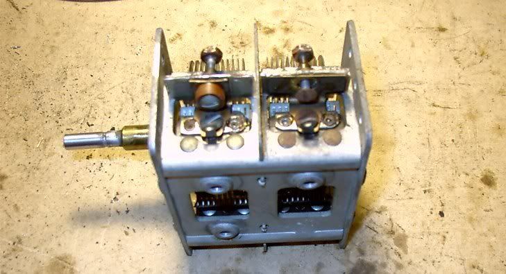


Sooner or later I'll figure out how to post the final picture.
Sorry for the inconvenience.
Terry F

Yep, that should do fine in the interim , later you might even come up with a bakelite rod and cut off a section to drill a center hole thru and make a replacement for the RF section aadditionally.
73's de Edd.
Are the capacitor bypassing sections resolved, otherwise I can see why there are spurious oscillations in the mixer stage.
73's de Edd
:Mentor and Master Edd,
:
:My quarterly report (March 31 is the end of the first quarter you know):
:
:I have taken five steps forward and several back. Here goes - steps forward:
:
:Several weeks ago I realized the multiplicity of Philco schematics and decided to go with #164-A which is the latest information in the packet that I received from Chuck Schwark and the most logical.
:
:(Philco finished their - "lets put this component in, then lets take it out excercises".)
:
:So, 164-A has the most removals of components and the fewest additions. It was interesting to follow the engineering change history from run to run and year to year for the same set.
:
:From there, as you requested I checked:
:
:All of the electrolytic caps are OK - voltage OK.
:
:Caps A,B,C and D in the metal can were checked with each cap disconnected from the tie down point and a DVM check to ground from tie point - all showed infinity on ohms scale, so these look OK.
:
:At the 51K resistor, a negative voltage is present on both sides of the resistor More negative on the cathode side which is coming directly off the bias resistor same as Thomas Dermody's set. This also eliminated the cap/resistor, too.
:
:When tracking down the cap "C" #20 I discovered a major mistake on my part with the B+ voltage connection to the 1st IF transformer - missing, so I corrected it.
:
:I felt pretty good about the set at that time, but still couldn't get stations to tune.
:
:Steps backwards:
:
:the grid cap of the 6A7 replacement tube received with a loose cap. Had to order a replacement and it arrived yesterday and was installed. [The #75 and the #78 were replaced as well.] What the heck.
:
:The tuning condensor started to slip and I removed it to clean. I noticed the insulator on the trimmers was broken, then it fell apart.
:
:Hopefully this will be the picture of what I now have:
:
:: :
:
:If the picture doesn't show, just copy to to your Internet browser address bar.
:
:The one "brown Bakelite" insulator on the trimmer was shot. I plan to replace it, if this is OK, with several stacked "fibre washers", then reassemble and install the tuner.
:
:After that I will go back to square one 1N34/Cap tester combination and see where I end up.
:
:Does this approach sound logical?
:
:Thanks in advance for all of your help.
:Terry F
It's been a while, but here is my progress:
Step one audio - results as expected (cricket-put-putt-speed boat, etc).
Step two
Received local 50,000 watt clear channel KMOX St. Louis - weak, but the speech was audible. I verified the station with another am radio to make sure it was KMOX
Step three
Received KMOX 1120 again, louder this time and another station about 1400
Step four
OK but KMOX 1120 was weaker this time
Step five
Recived 630 am KTRS Cardinal baseball game !! - NOT KMOX at 1120
Step six
Lost it all.
Is the second IF tfx the culprit?
Thank you in advance for all of your help. I feel close on this one.
Terry F

What timing, just as I had found 3 steatite washers that I had stashed away and just now uncovered, since I assume that your holdup was the excess tweaking upon the tuning condensers trimmer capacitors and the splitting in half of one of those insulators. I was just about ready to either ask for the dimensions and pull out the jewelers lathe and turn 2 new ones from Bakelite, Teflon or Delrin Rod stock or locate these steatite units that I knew that I had…some…where? Heavy on the where !
Now in looking back at the sleuthing down of the elusive RF, seems like that you got to step 5 OK which would be the 1st grid of the #78 I.F. amplifier and you’re looking for the 460 signal fresh off the mixers plate circuitry. Now since you
are receiving yet another station of KTRS at 630Kc along with the KMOX at 1120, does the dial calibration seen to be approximately close, on those quite separate stations SINCE you have had the tuning condenser totally pulled, along with that insulator being replaced. I am basically wondering about the closeness of tracking since one and possibly both trimmer adjustments might not have been restored to an optimal tracking setting, to get the very strongest 460 I.F. signal.
Any how, hoping for the best on that aspect, you might now initially do a powered down ohmmic testing of the second IF transformer windings and then the powering up of the set and confirm the plate and screen voltages on the #78 tube.
Just don’t expect it, but the #78 would be an easy unit to sub in another unit, since I think that you have another from a dupe set .
ZUJing…
73's de Edd
Oooops. You were right, the second IF transformer had a bad set of windings:
should be 34 ohms and 85 ohms.
I got 37 ohms and 45 ohms.
So, I replaced the transformer from my other spare chassis and it read OK on ohms. Powered up the set and got the following on 78 voltages:
plate = 282 VDC
screen = minus 1.4 VDC
No reception but a lot of high volume crackling.
Should I go back to the 1N34 diode sluething?
As always, thank you for your invaluable help.
Terry F
I haven't been following this but screen on a 78 tube should be positive, maybe 100 volts. Since you read a slightly negative voltage screen resistor to B+ may be open?
Norm
:I was able to scavenge an inslator from my "spare" chassis, so this is mechanically correct now.
:
:Oooops. You were right, the second IF transformer had a bad set of windings:
:
:should be 34 ohms and 85 ohms.
:I got 37 ohms and 45 ohms.
:
:So, I replaced the transformer from my other spare chassis and it read OK on ohms. Powered up the set and got the following on 78 voltages:
:plate = 282 VDC
:screen = minus 1.4 VDC
:
:No reception but a lot of high volume crackling.
:
:Should I go back to the 1N34 diode sluething?
:
:As always, thank you for your invaluable help.
:Terry F
As Norm said there should be positive voltage on the screen of the 78 tube (pin 3). Might want to check resistor R24 a 25K resistor and the cap .05 mfd from the screen to ground/chassis. If R24 is open or has greatly increased in value there will not be positive voltage on the 78 screen (pin 3) and also on G3,G5 grids of the 6A7 (pin 3).
Radiodoc
*****************
:I was able to scavenge an inslator from my "spare" chassis, so this is mechanically correct now.
:
:Oooops. You were right, the second IF transformer had a bad set of windings:
:
:should be 34 ohms and 85 ohms.
:I got 37 ohms and 45 ohms.
:
:So, I replaced the transformer from my other spare chassis and it read OK on ohms. Powered up the set and got the following on 78 voltages:
:plate = 282 VDC
:screen = minus 1.4 VDC
:
:No reception but a lot of high volume crackling.
:
:Should I go back to the 1N34 diode sluething?
:
:As always, thank you for your invaluable help.
:Terry F
Here goes:
My error on reporting a minus voltage before. It was really positive and over 100VDC
78 is as follows:
Plate = 285 VDC - pin 2
SG = 112 VDC - pin 3
SP = -1.4 VDC - pin 4
K = -1.4 VDC -pin 5
CG = 281 VDC (this one bothers me as it is the grid cap of the tube)No wonder I got knocked stiff from this one.
6A7 (for those interested)
Plate = 280 VDC - pin 2
G3/5 = 70 VDC - pin 3
G2/3 = 163 VDC - pin 4
G1 = -37 VDC (Is this the oscillator?) - pin 5
K = 1 1.3 VDC - pin 6
G4 = grid cap is -2.4VDC
Hope this helps. I still get loud crackling, but no audible stations received.
Thanks as always for your invaluable help and assistance.
Terry F
If Grid #1 has high voltage the tube is oscillating. Does your 78 have a tube shield?
Norm
:All,
:
:Here goes:
:
:My error on reporting a minus voltage before. It was really positive and over 100VDC
:
:78 is as follows:
:Plate = 285 VDC - pin 2
:SG = 112 VDC - pin 3
:SP = -1.4 VDC - pin 4
:K = -1.4 VDC -pin 5
:CG = 281 VDC (this one bothers me as it is the grid cap of the tube)No wonder I got knocked stiff from this one.
:
:6A7 (for those interested)
:Plate = 280 VDC - pin 2
:G3/5 = 70 VDC - pin 3
:G2/3 = 163 VDC - pin 4
:G1 = -37 VDC (Is this the oscillator?) - pin 5
:K = 1 1.3 VDC - pin 6
:G4 = grid cap is -2.4VDC
:
:Hope this helps. I still get loud crackling, but no audible stations received.
:
:Thanks as always for your invaluable help and assistance.
:Terry F
The control grid cap of the 78 definitely should not have 280 volts on it. Remove the grid cap and measure from the tube cap for the voltage and then from the grid connector from the IF transformer. If the voltage appears from the tube cap, the 78 may be shorted internally. If from the grid connector from the IF, then the IF transformer may be shorted from primary to secondary or perhaps the wires inside the IF transformer have lost their insulation and have shorted together putting the voltage from the plate of the 6A7 on the control grid of the 78.
Radiodoc
**************
:All,
:
:Here goes:
:
:My error on reporting a minus voltage before. It was really positive and over 100VDC
:
:78 is as follows:
:Plate = 285 VDC - pin 2
:SG = 112 VDC - pin 3
:SP = -1.4 VDC - pin 4
:K = -1.4 VDC -pin 5
:CG = 281 VDC (this one bothers me as it is the grid cap of the tube)No wonder I got knocked stiff from this one.
:
:6A7 (for those interested)
:Plate = 280 VDC - pin 2
:G3/5 = 70 VDC - pin 3
:G2/3 = 163 VDC - pin 4
:G1 = -37 VDC (Is this the oscillator?) - pin 5
:K = 1 1.3 VDC - pin 6
:G4 = grid cap is -2.4VDC
:
:Hope this helps. I still get loud crackling, but no audible stations received.
:
:Thanks as always for your invaluable help and assistance.
:Terry F
I checked the chassis to the top of the 78 (less the grid cap) and measured 1.9VDC.
I then measured the chassis to the grid cap (disconnected still from the 78 tube) and got 271VDC.
I do not find any short between the secondary to the primary of the IF tfx's (either one of the tfx's).
Thank you for your valuable assistance.
Terry F
As I said before, there definitely should not be a high positive voltage (B+) on the grid of the 78. The circuit feeding the grid thru the IF transformer secondary is the AVC circuit from the volume control thru a 2 meg resistor. If the high voltage is on the grid of the 78, then it is probably on the grid cap of the 6A7 too. That may account for the 11 volts measured on the 6A7 cathode instead of the 3 volts called out on the schematic. You may want to check out the AVC circuit and see if there are any connections to it from the radio's B+. Look for misswiring or solder bridges between terminal strips and etc. Somehow B+ voltage is getting there where it should not be.
Radiodoc
***************
:Radiodoc,
:
:I checked the chassis to the top of the 78 (less the grid cap) and measured 1.9VDC.
:
:I then measured the chassis to the grid cap (disconnected still from the 78 tube) and got 271VDC.
:
:I do not find any short between the secondary to the primary of the IF tfx's (either one of the tfx's).
:
:Thank you for your valuable assistance.
:
:Terry F
Do you have a oscilloscope? Look at the top connection on your 78 tube.
Even though you read a high DC voltage it can't be there. If excessive positive DC voltage was applied to grid #1 the tube would draw very high current and probably burn out. If it didn't burn out cathode voltage would be much higher.
Voltage seen on top of your 78 tube should also be on the 6A7. They are connected together through coils. Check continuity between these two tube tops. IF Transformer #16 may be open.
Norm
:Terry F,
:
:As I said before, there definitely should not be a high positive voltage (B+) on the grid of the 78. The circuit feeding the grid thru the IF transformer secondary is the AVC circuit from the volume control thru a 2 meg resistor. If the high voltage is on the grid of the 78, then it is probably on the grid cap of the 6A7 too. That may account for the 11 volts measured on the 6A7 cathode instead of the 3 volts called out on the schematic. You may want to check out the AVC circuit and see if there are any connections to it from the radio's B+. Look for misswiring or solder bridges between terminal strips and etc. Somehow B+ voltage is getting there where it should not be.
:
:Radiodoc
:***************
:
:
::Radiodoc,
::
::I checked the chassis to the top of the 78 (less the grid cap) and measured 1.9VDC.
::
::I then measured the chassis to the grid cap (disconnected still from the 78 tube) and got 271VDC.
::
::I do not find any short between the secondary to the primary of the IF tfx's (either one of the tfx's).
::
::Thank you for your valuable assistance.
::
::Terry F
Should I go back to the 1N34 diode sluething?
Not ‘til the high voltage on the Firstus Gridamus of the #78 is resolved. I did not quite catch the time frame of exactly WHEN that excess voltage was detected, at the point…before or after…. the 2nd IF xfmr got changed out ?
There also seems to be the question of where it is coming from...... the first IF transformer or the second IF transformer. If from the 1st IF transformer that would be one dynamic voltage leaking across, since the transformers B+ supply points are fed from one hefty, sub B+ level. If coming in backwards from the second I.F. circuitry, quite that high of a voltage level would probably not be possible, what with the secondary of that transformer having a closed loop thru the total resistance of the vol-you-me control to ground, and then having to flow back thru the resistance of R21 a 2 meg resistor, PLUS the given G4 voltage of the 6A7 does not reflect a higher than normal voltage level coincidentally along with the high level that is on the #78’s first grid.
No chance of a miswire on the changeout of the 2nd IF xfmr, was there ?
Heck…..just monitor the excess voltage on the 78’s 1st grid and then clip the B+ line feeding to the 1st I.F.transformer and then see if it drops to zip. If so, concentrate more on that transformer…. or the second one , if voltage didn’t drop. Then, excluding a miswire or unnoticed short, the logical reasoning for that level of B+ ending up into that grid circuitry is leakage inside an IF transformer. Monitoring the unexpected B+ on the grid and then the additional shorting of that point to ground thru a 1 meg resistor would answer as to whether that voltage level was a dynamic or static level (leakage).
73's de Edd
Edd might have something mentioning IF Transformer was changed. Any chance it's wired wrong? B+ could get wired to the grid if wiring isn't correct.
Norm
:
:
:
:
:
:
:
:
: Should I go back to the 1N34 diode sluething?
:
:
:
:
:Not ‘til the high voltage on the Firstus Gridamus of the #78 is resolved. I did not quite catch the time frame of exactly WHEN that excess voltage was detected, at the point…before or after…. the 2nd IF xfmr got changed out ?
:
:There also seems to be the question of where it is coming from...... the first IF transformer or the second IF transformer. If from the 1st IF transformer that would be one dynamic voltage leaking across, since the transformers B+ supply points are fed from one hefty, sub B+ level. If coming in backwards from the second I.F. circuitry, quite that high of a voltage level would probably not be possible, what with the secondary of that transformer having a closed loop thru the total resistance of the vol-you-me control to ground, and then having to flow back thru the resistance of R21 a 2 meg resistor, PLUS the given G4 voltage of the 6A7 does not reflect a higher than normal voltage level coincidentally along with the high level that is on the #78’s first grid.
:
:No chance of a miswire on the changeout of the 2nd IF xfmr, was there ?
:
:Heck…..just monitor the excess voltage on the 78’s 1st grid and then clip the B+ line feeding to the 1st I.F.transformer and then see if it drops to zip. If so, concentrate more on that transformer…. or the second one , if voltage didn’t drop. Then, excluding a miswire or unnoticed short, the logical reasoning for that level of B+ ending up into that grid circuitry is leakage inside an IF transformer. Monitoring the unexpected B+ on the grid and then the additional shorting of that point to ground thru a 1 meg resistor would answer as to whether that voltage level was a dynamic or static level (leakage).
:
:
:
:
:73's de Edd
:
:
:
:
:
I monitored the voltage on the 78 grid cap and clipped the lead, which brought the voltage to about 1.5 VDC (close enough to zero for me).
So, I exhumed the 1st tfx from the chassis and checked the circuits with a VTVM, DVM and analog meter. I could not find any short between the primary and secondary. The grid cap lead rang out at 46 ohms which is about the same as that section of the tfx, so I assume this is correct.
So..... I re-installed said tfx and powered it up. Voltage was back to 272 VDC.
So..... I put a test lead to the grid cap of the 78, connected the other end to a 1 meg resistor and attached another test lead to the other end of the 1 meg resistor and took it to chassis ground.
The grid cap reading was 272 VDC up to one side of the resistor. Then the voltage dropped to zero VDC on the side of the resistor that was grounded.
I do not know, and plead ignorance to your meaning of static/dynamic. Can you clarify?
So... after many times of looking at the schematic...and wondering what is wrong with this radio....I am curious of the schematic for bulletin #164-A which is the schematic I have been working on all along.....it would appear that the actual factory wiring and the resistance readings of connections to condensor #17 and #18 are reversed. The plate of the 6A7 should connect to the 34 ohm coil and the grid cap of the 78 should connect to the 47 ohm side. I will investigate tomorrow and let you know what I find.
As always, thanks in advance for your invaluable help.
Terry F
I still think there is a miswiring somewhere putting B+ voltage on the 78 grid and probably the 6A7 grid. I am pretty sure there is B+ of sorts on the 6A7 mixer grid (tube cap) as you stated there was 11 volts on the cathode of the 6A7 tube instead of 3 volts telling me that there is a positive voltage on the mixer grid of the 6A7. You may want to carefully check the AVC circuit for miswiring to a B+ source. Bascially (I am using the schematic on this site) the AVC starts at one side of the volume control and goes thru a 2 meg resistor where it branches out to and thru the secondary of the 1st IF transformer (the one between the 6A7 and 78 tubes) and then on to the secondary of the antenna transformer thru it on to the grid (tube cap) of the 6A7. Except for a .05 mfd cap to ground (I think that is the value, the print is not real good) that is the AVC line and nothing else should connect to it. Incidentally, a static voltage probably would not almost take you to your knees as you mentioned when you got across the 78 grid and ground.
Radiodoc
***************
:Master and Mentor Edd,
:
:I monitored the voltage on the 78 grid cap and clipped the lead, which brought the voltage to about 1.5 VDC (close enough to zero for me).
:
:So, I exhumed the 1st tfx from the chassis and checked the circuits with a VTVM, DVM and analog meter. I could not find any short between the primary and secondary. The grid cap lead rang out at 46 ohms which is about the same as that section of the tfx, so I assume this is correct.
:
:So..... I re-installed said tfx and powered it up. Voltage was back to 272 VDC.
:
:So..... I put a test lead to the grid cap of the 78, connected the other end to a 1 meg resistor and attached another test lead to the other end of the 1 meg resistor and took it to chassis ground.
:
:The grid cap reading was 272 VDC up to one side of the resistor. Then the voltage dropped to zero VDC on the side of the resistor that was grounded.
:
:I do not know, and plead ignorance to your meaning of static/dynamic. Can you clarify?
:
:So... after many times of looking at the schematic...and wondering what is wrong with this radio....I am curious of the schematic for bulletin #164-A which is the schematic I have been working on all along.....it would appear that the actual factory wiring and the resistance readings of connections to condensor #17 and #18 are reversed. The plate of the 6A7 should connect to the 34 ohm coil and the grid cap of the 78 should connect to the 47 ohm side. I will investigate tomorrow and let you know what I find.
:
:As always, thanks in advance for your invaluable help.
:
:Terry F
I think I found the problem: the 1st IF tfx is rotated 180 degrees from normal (as compared to my other chassis).
The tfx has a tab with a hole that bolts to the chassis at 3:00 o'clock and wires at 10,2,4 and 8. The wires at 10 and 2 are the closest to the 6A7 and this is where they are connected to the plate, etc. Wires at 4 and 8 are for the condensors, which places these close to them. This location pattern keeps the wires as short as possible. The tab grabs the transformer as it sits inside the aluminum can and bolts into the chassis.
In looking at some old Philco documentation daubs of pait were used as identifiers (positioners). My 1st IF has a daub of paint (orange) to indicate the primary side, but the fact it is 180 degrees out of whack, puts the wires in the wrong location. I have another chassis and I compared the two and found this out, so essentially, the wiring of the secondary is going to the locations of the primary ergo the 6A7 plate voltage onto the grid cap. Two factory chassis wired differently. I guess the Philco factory guys saw the paint, knew which was what and wired it accordingly. I used the orientation and wire position and was wrong.
No wonder this problem has been so elusive for me. NOW I learned to VERIFY the coil resistance BEFORE I hook it up.
I will verify this today and advise.
Thanks in advance for all of your valuable help and assistance.
Terry F
I re-wired the 1st IF tfx to the correct coils (primary and secondary).
The voltage on the 78 grid cap dropped to -1.8VDC (as well as the 75 and 6A7)
No reception, but I get a loud motorboating at the low end of the AM dial (about 550KC to about 7000KC and a loud whistling at the high end of the dial from about 900KC and up.
As always, thanks in advance for your invaluable help.
Terry F
Well…. …..
…..
that seems to take care of some degree of the “mis wiring” aspect with the “Black Lavatory Deceiver” going bonkers..... portion.... to probably being solved with getting the IF’s back to a 460KHZ tuning again to stop the "botor moating".
Almost time to start sequentially RF probing again !
73's de Edd
So is that a yes?
Terry F
Yes, that is a condition go, considering that you can receive and work on some frequencies that are without any invasive motor boating action.
73's de Edd
Step two is much improved on reception of KMOX 1120 am, but now there is a background noise - not a howl or whistle (more like a high frequency buzzing). It gets worse the more I tune off of 1120 (either way).
I am relucatnt to proceed but will with your advice. I plan to check all of the caps in the condensor bank.
Thank you in advance for all of your help.
Terry F
Since you are now able to get a low band signal thru the receiver, it should now be possible to pump a 400 / 1000 Khz modulated RF signal thru the sets front end and peak up the IF’s to 460, since there have been so many IF transformer swap arounds involved . If you have no signal generator then you might just have to fudge a bit and have to tune in for optimum pick up of your receivable KTRS talk radio signal and then peak the IF transformers to it.
Then see what effect that had on your units breaking into onsets of spurious oscillation when tuning across the BCB.
Since you were weakly picking up signals at both the high and low end of the dial thru the “amplified crystal detector” we should expect to get to the same results again and then proceed on to the IF stage and probe to then see if some IF amplification is now possible.
I thought that your block of capacitors had already been rebuilt.
The most critical of its elements being the RF bypass condensers contained within, however if getting right down to it, one could have a condition of tuning a set into an onset of breaking into oscillation or motor boating and take an ~.05-.1 ufd /~500WVDC disc ceramic capacitor with short lead length and then do a test bypass to ground of the most critical bypass functions, which would be the screen grid of the 6A7 (block cap A section), the screen grid of the IF amp (block cap B section) and the B+ supply line feeding the IF transformers (block cap section C) and with the #75 plate supply decoupling (block cap D section), being the last on the list of criticality. That would give some idea, if questioning of adequate bypassing at that point was an issue.
ZUJing…
73's de Edd
I cannot thank you enough for all of your help. From you I have learned more about a super heterodyne radio that all of the Marcus-Levy books can offer.
Your idea on the 1N34 diode probing was just fantastic. I plan to use this on any future problem sets. The technique is simple, once you get the hang of it and believe me, I got it and will never be without it.
The only thing I missed was the chance to use the clarinet reed. Just kidding. I'll keep it as a reminder of all of the help you gave me.
THANK YOU!!!!!
Terry F
I found resistor #10 (from 6A7 cathode to condensor #13) loose. Resoldered it.
Removed the 1N34 diode and .001 cap attached to the grid of the 6A7 (since the buzzing went away).
Powered up the set and was actually able to tune in a low end radio station 630 am KTRS. If I tune higher I get some really loud motorboating and then silence up to the top of the dial.
No stations received in the higher frequencies, but I am glad the radio actually plays on its own. Any pointers from here? Am I terribly out of alignment?
Thank you for all of your invaluable help.
Terry F
Congrats on getting this far. Make sure all tube shields are in place and making good contact with the chassis.
Radiodoc
***************
:Eureka,
:
:I found resistor #10 (from 6A7 cathode to condensor #13) loose. Resoldered it.
:
:Removed the 1N34 diode and .001 cap attached to the grid of the 6A7 (since the buzzing went away).
:
:Powered up the set and was actually able to tune in a low end radio station 630 am KTRS. If I tune higher I get some really loud motorboating and then silence up to the top of the dial.
:
:No stations received in the higher frequencies, but I am glad the radio actually plays on its own. Any pointers from here? Am I terribly out of alignment?
:
:Thank you for all of your invaluable help.
:
:Terry F
Thanks! Tube shields are in place, but only the one low frequency station received.
Terry F
:
:Thanks! Tube shields are in place, but only the one low frequency station received.
:
:Terry F
Terry F,
You may want to do as Edd mentions earlier in this thread. Try using a .05 Mfd or so cap and try bypassing the caps in the cap bank A,B,C and D to chassis/ground. The first three are most important to prevent oscillation/feedback.
Radiodoc
****************
All by-pass caps changed. No difference.
My alternate chassis had a provision for a tube shield on the 6A7 and the chassis I have been working on didn't, so I placed a shield over the tube and a lot of the interference went away especially the loud crackling and most of the motorboating. It is not connected to the chassis other than just sitting there. This chassis doesn't have a provision for a tight fit.
One station (KTRS) which is 550KC, not 630KC as previously reported, is received loud and clear. Nothing higher. It is almost the only station all across the tuning band on am. It gets softer the higher I tune the dial. Other posts on ARF suggest the oscillator isn't working with this condition. I am not sure.
Last night I tried sw just for the heck of it and I did pick up some faint station (language undetectable) possibly Spanish. This was on the high end of the dial.
As always, any help is greatly appreciated.
Terry F
P.S. My speaker went dead and I replaced it with my alternate. The cone separated from the spider.
P.P.S Man, am I learning a lot about this radio and the theory after reading two Marcus and Levy books. It is frustrating at times, but a learning experience for sure.
The station at 550KHz is pretty close to the IF frequency of the radio. If the oscillator is not working, then tuning the tuning cap will make the signal louder and softer and the station will cover a good portion of the tuning range. Check the voltages on the 6A7 tube pins especially pin 4 and 5. Pin 4 should have a positive voltage on it, maybe 100 volts and pin 5 should have several volts negative if the oscillator is running. The untuned winding of the oscillator coil may be open (the 3.4 Ohm winding). It was quite common for oscillator coil windings to open up in old Philco radios.
Radiodoc
*****************
:Radiodoc,
:
:All by-pass caps changed. No difference.
:
:My alternate chassis had a provision for a tube shield on the 6A7 and the chassis I have been working on didn't, so I placed a shield over the tube and a lot of the interference went away especially the loud crackling and most of the motorboating. It is not connected to the chassis other than just sitting there. This chassis doesn't have a provision for a tight fit.
:
:One station (KTRS) which is 550KC, not 630KC as previously reported, is received loud and clear. Nothing higher. It is almost the only station all across the tuning band on am. It gets softer the higher I tune the dial. Other posts on ARF suggest the oscillator isn't working with this condition. I am not sure.
:
:Last night I tried sw just for the heck of it and I did pick up some faint station (language undetectable) possibly Spanish. This was on the high end of the dial.
:
:As always, any help is greatly appreciated.
:
:Terry F
:
:P.S. My speaker went dead and I replaced it with my alternate. The cone separated from the spider.
:
:P.P.S Man, am I learning a lot about this radio and the theory after reading two Marcus and Levy books. It is frustrating at times, but a learning experience for sure.
:
:
Pin 4 is about 180VDC and pin 5 varies from -45 VDC to -9.5VDC.
The variableness in the pin 5 reading comes from the tuning dial. As I turn the dial to a lower frequency the lower the voltage on that pin goes down and volume goes up.
I thought the tuner only changed capacitance and not resistance. I had the oscillator coil rewound by Ron Ramirez. How can I check for an open while the coil is in the set?
Thanks for all of your help.
Terry F
If there is voltage on pin 5, then the oscillator is working. The problem must be somewhere else.
Radiodoc
**************
:Radiodoc,
:
:Pin 4 is about 180VDC and pin 5 varies from -45 VDC to -9.5VDC.
:
:The variableness in the pin 5 reading comes from the tuning dial. As I turn the dial to a lower frequency the lower the voltage on that pin goes down and volume goes up.
:
:I thought the tuner only changed capacitance and not resistance. I had the oscillator coil rewound by Ron Ramirez. How can I check for an open while the coil is in the set?
:
:Thanks for all of your help.
:
:Terry F
I believe you mentioned you could tune in a station around 1120KHz. May try tuning it for best sound and try adjusting the two IF transformers by ear for loudest sound. I mention this only because I don't recall you mentioning you having a signal generator or aligning the IF transformers.
Radiodoc
**************
:Radiodoc,
:
:Pin 4 is about 180VDC and pin 5 varies from -45 VDC to -9.5VDC.
:
:The variableness in the pin 5 reading comes from the tuning dial. As I turn the dial to a lower frequency the lower the voltage on that pin goes down and volume goes up.
:
:I thought the tuner only changed capacitance and not resistance. I had the oscillator coil rewound by Ron Ramirez. How can I check for an open while the coil is in the set?
:
:Thanks for all of your help.
:
:Terry F
As I recall, though, the oscillator in my Philco 60 gave a rather high negative voltage over the entire band. I will have to check and let you know. Right now I'm too busy with finals. From what I can tell (voltages) the oscillator in your set is working, and so even if it isn't working well all over the band, it is most likely not the problem. What could be happening is that there could be a miswound or miswired coil, if you did anything with the coils, or there could be a missing capacitor, or an open capacitor, all of which might be causing the oscillator to run at a higher frequency than it should for the broadcast band. That would give you your low voltages, and would keep the radio from working, since the oscillator and antenna circuits wouldn't be in sync. at all. You might be able to tell by placing another radio nearby. The oscillator should track roughly 465KC above or below the frequency indicated on the dial. If it is a bit off, then it is probably just out of adjustment. If you can't even find it, then it might be really far off due to one of the reasons I gave above. It's worth a check.
T.
Thanks for the hint.
I did two things:
a) on your suggestion that there might be a missing/wrong component, I have been all over this radio. The only thing not verified with the Philco bill of material for the service bulletin 164-A was the compensating condensors.
I checked them and they did NOT agree with what was in my chassis. For example, one of the condensors was a 4000-J with a capacity range of 40-180 mmf. What I needed was a 4000-M with a capacitance of 15-130 mmf. This was for #17 variable condensor. So, I changed it out with one from my Philco spare parts kit.
b) I placed a funtioning Westinghouse W-209 next to the Philco and started adjusting the 1st IF, set until I got something.
I am now receiving stations up and down the am band. I even got a couple of sw stations tonight (weak but none the less there).
Wow! I feel like celebrating.
Thanks to you for all of your help and especially patience.
This post is CLOSED!
Terry F
Glad that you got your radio working, though. As I said before, your oscillator should track 465 KC above whatever signal you have tuned in. I believe that it tracks above, though it could track below. At any rate, to calibrate the radio without a signal generator, set that Westinghouse next to the Philco and set it to a frequency 465 KC above whatever signal you want to tune in. Adjust the oscillator until the Philco dial says the frequency you want (it is best to do this towards the high end of the band) with the oscillator coming in clearly through the Westinghouse (it should come in as a dead spot).
Once the oscillator is calibrated properly, adjust the antenna trimmer so that distant signals at the high end of the band come in well. Then adjust the IF transformers so that signals around 600 KC come in where they should. Philco 60s usually have a padder, so adjust the oscillator padder at the low end of the dial as well. Re-check the high end of the band and then re-check the low end of the band again. Repeat until all is the way you want it. Then proceed to the short wave band. Adjust only the antenna and oscillator adjustments. The short wave will have an antenna adjustment and an oscillator adjustment, both which are to be made at the high end of the short wave band. Standard time signals come in conveniently at 2.5 and 5 megacycles. I believe that they come in best in the afternoon, though I forgot. You won't be able to receive them during certain times of the day. The short wave band, as I remember, doesn't have a padder, so no compensation is available for the low end of the band. If everything was set up well for the broadcast band, though, the low end should fall into place fairly well.
T.
You have been super! You helped me on my Majestic several years ago and now this Philco. I really appreciate the assistance.
Terry F