That extra RF stage makes signals stronger but also it seems more quiet between stations.
And when I re-coned that little 5" speaker (though it didn't need it)
Wow!!
..what a great improvement in bass response too!!
The only slight but very nice change that I made to the audio tone...was to put another tone cap .001uf from the plate of the 12SQ7 to B-.
You'll also notice that this radio does have a field coil... but only 300 ohms... ( usually in transformer radios though ..they are about 1500 ohms or more).
It also uses a three-stage power supply filter
( components in yellow)
And it distributes to B+ levels in a strange way.
The red B++ goes to the output tube and the IF amp plate.
.. and all the blue B+ goes to the rest.
In all respects this is a very fine radio.
I haven't redone or touched the cabinet yet... next week maybe... it won't need much.
But I love the performance and the deep rich sound. So maybe this will be a "keeper" ...
BTW it was made during the year I was born or there abouts 1942!
Nice to see how well things were done and how nice and long the design lasts....( it will out live me for sure now...lol)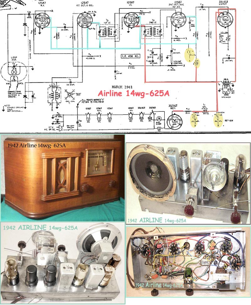
T.
T.
What kind of oil are you referring to - cooking oil? You spread it on the outer edge of the cone? I have some Airline speakers that I'm not happy with either.
Thanks
Bill
:Beautiful radio. I have noticed that the Airline speakers are a bit stiff. A bit of oil mixed with dish detergent rubbed into the outer edge really helps, though your cones make them sound even better. I have also noticed that 6 tube radios are a bit quieter between stations, except at night perhaps. I believe that this is because of the rejection of image signals. If the 6 tuber either has a wave trap or a tuned front end, image and harmonic signals will be rejected. On most of my 5 tube radios, if I hunt enough, I will find duplicates of certain stations all over the dial.
:
:T.
:Now this week's effort is a WARDS Airline 14wg-625A six tuber... that is really wonderful sounding.
:
:That extra RF stage makes signals stronger but also it seems more quiet between stations.
:
:And when I re-coned that little 5" speaker (though it didn't need it)
: Wow!!
:..what a great improvement in bass response too!!
:
:The only slight but very nice change that I made to the audio tone...was to put another tone cap .001uf from the plate of the 12SQ7 to B-.
:
:You'll also notice that this radio does have a field coil... but only 300 ohms... ( usually in transformer radios though ..they are about 1500 ohms or more).
:It also uses a three-stage power supply filter
: ( components in yellow)
:And it distributes to B+ levels in a strange way.
:
:The red B++ goes to the output tube and the IF amp plate.
:.. and all the blue B+ goes to the rest.
:
:In all respects this is a very fine radio.
:
:I haven't redone or touched the cabinet yet... next week maybe... it won't need much.
:
:But I love the performance and the deep rich sound. So maybe this will be a "keeper" ...
:BTW it was made during the year I was born or there abouts 1942!
:Nice to see how well things were done and how nice and long the design lasts....( it will out live me for sure now...lol)
:
Thanks... but No it didn't look anywhere near this good.
....lol...
Nope..That chassis represents a lot of detailing and scrubbing.
Many times I do have to use Emory cloth and wire brushes... but this one seems to have a nice zinc plating or something like that, that only needed a good scrubbing/washing and then was brushed to a luster with a very short stiff hog's hair brush and in some places a brass brush.
A quick comment about low resistance field coil... These are AC/DC radios and don't have much B+ voltage. If a higher resistance field was used voltage to tubes would be too low.
A radio with 300 volts can easily drop 100 across the field but an AC/DC radio wouldn't have any voltage left.
Norm
::That's a beautiful radio, was the chassis already that clean, rust free, & shiny?
:
:Thanks... but No it didn't look anywhere near this good.
:....lol...
:Nope..That chassis represents a lot of detailing and scrubbing.
:Many times I do have to use Emory cloth and wire brushes... but this one seems to have a nice zinc plating or something like that, that only needed a good scrubbing/washing and then was brushed to a luster with a very short stiff hog's hair brush and in some places a brass brush.
:
:
: A quick comment about low resistance field coil... These are AC/DC radios and don't have much B+ voltage. If a higher resistance field was used voltage to tubes would be too low.
:
: A radio with 300 volts can easily drop 100 across the field but an AC/DC radio wouldn't have any voltage left.
:
:Norm
Hey Norm...
:That's an interesting point Norm.
I always just figured that in order to get enough magnetizing power the early field coils were wound with a bunch of fine wire ... and that, perhaps, the secondary effect was that that much wire also happened to create that high 1500 ohms or so resistance... there fore I assumed they HAD to have higher voltage winding 2ndaries to start with enough voltage to anticipate a significant drop from all that wire/ ohmage... so as to end up with a reasonable B+.
Otherwise why bother to drop so many volts over the fied coil?
If they could have wound enough magnetisim with less ohmage why didn't they do that and reduce the secondary transformer high voltages?
I left this question on ARF as well but thought it might be of interest here too. Thomas has tried to shed light on this before but I'm not sure of my understanding on it.
So here's sort of a simple question I've never really understood.
What is the reasoning for the choice of or the reason for the difference or the relationship of the coupling cap value on the input to the detector 1st audio (12sq7) and the other coupling cap from the 12SQ7 to the output amp.??
Quite often these two caps are the same value (.01uf) but often times I've seen the detector input cap at .002 or .004 uf.
In the schematic as shown in my previous post of the Airline 625A it uses a .004 and a .01.
Can anyone explain why ?
Also why is the input coupling cap to the 12SQ7 always on the cathode input from the IF via the volume pot and not placed instead on the diode input to the 12SQ7 from the IF?
:
However, for the output tube, where a lot of current is handled, the bias resistor must be kept lower in value, to hold the grid more tightly to where it is supposed to be. A higher capacitance value is necessary in order to get enough bass. Also, better tonal response usually results from smaller grid resistor values. I've noticed that when the grid or plate resistances are allowed to be high, the high end tends to suffer.
There must be a more technical explanation than this, though. If one was to study an amplifier really thoroughly (more-so than I have), one could come up with numeric reasons....more exact reasons.
T.
If manufacturers use the same value cap in both locations they may not want to stock different caps?
Norm
:Hopefully someone else will come up with a better explanation, but from what I can see, using higher grid bias resistor values allows for more gain. With higher values, you will get more bass. To compensate, use a smaller value input capacitor.
:
:However, for the output tube, where a lot of current is handled, the bias resistor must be kept lower in value, to hold the grid more tightly to where it is supposed to be. A higher capacitance value is necessary in order to get enough bass. Also, better tonal response usually results from smaller grid resistor values. I've noticed that when the grid or plate resistances are allowed to be high, the high end tends to suffer.
:
:There must be a more technical explanation than this, though. If one was to study an amplifier really thoroughly (more-so than I have), one could come up with numeric reasons....more exact reasons.
:
:T.
:
:If manufacturers use the same value cap in both locations they may not want to stock different caps?
:
:Norm
:
:
Thank you Norm... that DOES finally start to make swense to me....lol
I wasn't thinking of it in RC time constants... but only as Xc... frequency passing.... but certainly now that I think...DUH... that bias resistor does form an R-C arrangemet.
OK Norm.. Thanks... NOW...now can you also try to shed some light on the lower ohm field coil in the AA5 vs high ohm field coil found in transformer sets as in my previous respose?
As mentioned before AC/DC radios don't have as much voltage to start with so can't use as high of resistance field.
Most consoles are AC and have large speakers. These large speakers require a stronger magnetic field. AC/DC radios are often small table models with 4" or 5" speakers. Less magnetic field is required.
Something else to think about. AC/DC radios using 50L6 or 50C5 operate on low voltage but draw around 50 ma plate current. An AC radio with 6K6 draws maybe 40 ma.
The more current drawn less resistance is required for the field considering both use the same size wire. It's amp/turns that give a magnetic field.
Norm
::That's correct. The first stage can use a smaller coupling cap since it feeds into a higher impedance circuit, high value grid resistor. The next stage usually has a lower value grid resistor so requires a larger coupling cap. It's mostly about time constants. If the coupling cap isn't large enough low frequency response will be lost.
::
::If manufacturers use the same value cap in both locations they may not want to stock different caps?
::
::Norm
::
::
:Thank you Norm... that DOES finally start to make swense to me....lol
:
:I wasn't thinking of it in RC time constants... but only as Xc... frequency passing.... but certainly now that I think...DUH... that bias resistor does form an R-C arrangemet.
:
:OK Norm.. Thanks... NOW...now can you also try to shed some light on the lower ohm field coil in the AA5 vs high ohm field coil found in transformer sets as in my previous respose?
:
: As mentioned before AC/DC radios don't have as much voltage to start with so can't use as high of resistance field.
:
: Most consoles are AC and have large speakers. These large speakers require a stronger magnetic field. AC/DC radios are often small table models with 4" or 5" speakers. Less magnetic field is required.
:
: Something else to think about. AC/DC radios using 50L6 or 50C5 operate on low voltage but draw around 50 ma plate current. An AC radio with 6K6 draws maybe 40 ma.
:
: The more current drawn less resistance is required for the field considering both use the same size wire. It's amp/turns that give a magnetic field.
:
:Norm
:
Ok NORM...thank you.
HUMMM. I'll try to cogitate on that a while.
I don't think of "lrge" speakers... all I work on is table models. The transformer types all seemed to have 1500 ohm or higher field coils....(6k6 or 6l6 or 41/42/43 etc) even for only a 5" speaker.
It wasn't only the other day I saw my 1st AA6 radio with a 35L6 using a 300 ohm field coil on a 5" speaker.... that seemed to wound about the same physical size as the transformered field coil radios.
So how did the two speakers seem to look the same sized winding ( approximately) and have such a difference in ohmage?
1/3 compared to the other.
Did it depend on the wire gauge ?
It would seem both speakers required the same magnetic force...right?
but you are suggesting that it is based on the output tube's current draw... to produce the sound well vs the amount or difference in the magnetic field?
...lol Hope I'm not confusing you more Norm... sorry
So I couldnt
If both speakers have the same size field but different resistance it's due to wire size. Larger wire size will have lower resistance and fewer turns. It wouldn't get as hot with the same amount of current.
There are all kinds of ways fields were wired in radios. Some were right across B+ to B-. I've found some speakers with tapped fields that have one section of the coil open. They seem to work ok using just the tap and one side.
Speaker fields are like output transformers, not that critical. A wide range of resistance will operate just having an effect on radio voltage. Too high and there won't be much B+ voltage in AC/DC radios.
Norm
::Hi Peter
::
:: As mentioned before AC/DC radios don't have as much voltage to start with so can't use as high of resistance field.
::
:: Most consoles are AC and have large speakers. These large speakers require a stronger magnetic field. AC/DC radios are often small table models with 4" or 5" speakers. Less magnetic field is required.
::
:: Something else to think about. AC/DC radios using 50L6 or 50C5 operate on low voltage but draw around 50 ma plate current. An AC radio with 6K6 draws maybe 40 ma.
::
:: The more current drawn less resistance is required for the field considering both use the same size wire. It's amp/turns that give a magnetic field.
::
::Norm
::
:Ok NORM...thank you.
: HUMMM. I'll try to cogitate on that a while.
:
:I don't think of "lrge" speakers... all I work on is table models. The transformer types all seemed to have 1500 ohm or higher field coils....(6k6 or 6l6 or 41/42/43 etc) even for only a 5" speaker.
:
:It wasn't only the other day I saw my 1st AA6 radio with a 35L6 using a 300 ohm field coil on a 5" speaker.... that seemed to wound about the same physical size as the transformered field coil radios.
:
:So how did the two speakers seem to look the same sized winding ( approximately) and have such a difference in ohmage?
:1/3 compared to the other.
:Did it depend on the wire gauge ?
:It would seem both speakers required the same magnetic force...right?
:
:but you are suggesting that it is based on the output tube's current draw... to produce the sound well vs the amount or difference in the magnetic field?
:
:...lol Hope I'm not confusing you more Norm... sorry
:
:
:
:So I couldnt
:
:
:
:
T.