But I forgot to turn off the gas!!!
I heard my alarm going off .
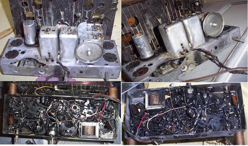
Those old rubber-coated wires had caught fire alright!!!
....and when I opened the oven door there were flames shooting right up through the IF cans !!
....and the whole house had 2 feet of smoke on the ceiling.
Well after a night of cleaning the kitchen and then my fire insurance folks paid to have a team come here and scrub the whole house for a week.
That Zenith chassis seemed like it was a gonner though. And I sadly stuck it in my junk box out in the garage.
But then months later I stole the (blackened but not ruined) IF cans from it to put into an old Howard 910 that had both IF cans with open windings.
They worked for that Howard just fine.
Then I met a guy on-line from Brazil who said he could re-wind those old Howard IF cans. So I sent them to him.
In the mean time I told him about the Zenith fire and he offered to completely rebuild that Zenith chassis for me.... for what amounted to about $150 !!
So I sent him everything that was burned and all the good parts TOO that weren't burned... including the speaker, dial face, dial cover, wood cabinet etc.
It took him quite a long while but he did do a great job.
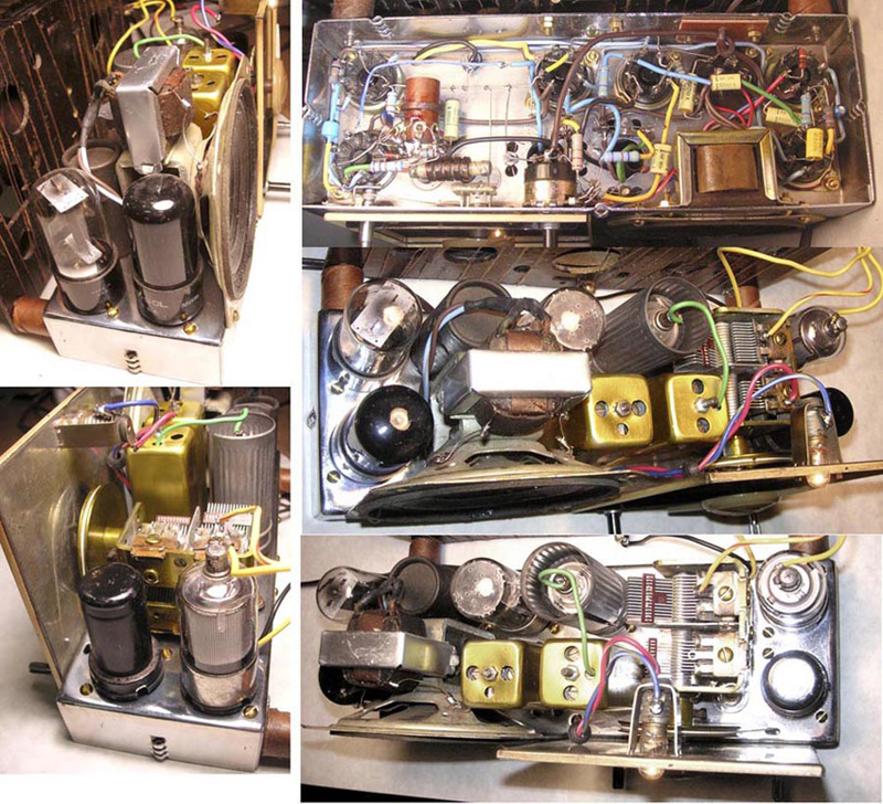
He completely chromed the old burned-black chassis and he also gold-anodized the Howard IF cans and re-wound the coils.
He put those re-wound Howard IFs into the Zenith and all new tube sockets, wires, components... even the oscillator coil and the wave trap... ALL new!
And his wiring skills are beautiful.. almost artistic.
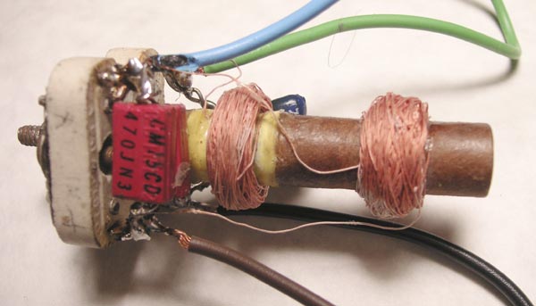
Turns out he didn't wind the IFs exactly correctly.. 700uh instead of 1.4 mh...so I had to pad the trimmers accordingly. I also had to pad the local oscillator by adding 20pf to get it into alignment... but now this thing rocks
PS - the restored chassis looks great...
T.
:
:T.
Thomas :
I already have the IF cans all back together and in the unit now.
But they do look pretty nice. Not exactly as square-edged and tightly bundled as the original but still he used litz wire in a reasonably tight or narrow bundle that looks a little more "scramble-wound" ...and not as much "inter-woven" .....if you know what I mean.
Of the two bad transformers ...only 3 windings needed replacing/rewinding. He said he tested the 'Q' on the new windings and something else ( I don't get his broken English/Portuguese very well)
But they did not work properly when I got the radio.
Thank God for my handy dandy $125 Inductor/Capacitor tester.
I measured the one original "good" winding for comparison as 1.4 mh.
And his new windings were all close to only 750 or 800 uh.
So I had to do some experimenting to get everything working. Esp since the local oscillator was off too.
He shipped it without any tubes so I don't know if he tested the complete radio at all ...since he said he didn't have a 12J7G to test it with.
When I put the tubes in it here,... it DID work "sort-of" ...but all I got was the one nearby 50kw strong station everywhere on the dial.
Luckily I have a couple of spare test IFs transformers here to substitute with while I got the local oscillator working correctly. Then I fixed each IF one at a time.
I located an on-line L/C resonant calculator to come up with the approximate correct values of capacitance to use with 800uh.
The built-in trimmers go up to 100pf .. so I had to parallel values that allowed the trimmer to trim with some range.
Out on the bench I fed 455khz into one winding while observing the other windings ability to resonate on my scope.
Of course they change when the coils are back in the cans and in the circuit. So there was a lot of trial and error.
I had to add about 50-80pf across each trimmer cap.
:
:T.
My wife can spend $150 for a make over and not look that good.
Lewis
P. S. I never sent this.
Well, even with the coil troubles, I think that $150 was a steal! With the wiring and plating, I'd expect to pay several hundred dollars. Plating shops in town want to charge me a minimum of $65 to re-plate my brass electrolier. I don't even bother. Maybe someday. There are other items I'd like plated, too, but it isn't worth it.
T.
I've found references to this site with quotes and names on Google. She already knows!!!
marv
::WOW! Nice chassis! All for $150?????? Show us the IF coils. Do they look nice?
::
::T.
:
:My wife can spend $150 for a make over and not look that good.
:Lewis
:
:P. S. I never sent this.
Here's a picture of one of those IFs he re-wound for me.
I had to add those padder caps... clumsy soldering...lol
Interesting caps you have in place. I still haven't gotten around to making a mold. I want to make a thin small wooden hinged box (with alignment pins), and in the box (or perhaps boxes) I want molds for resistors and condensers, so that I may mold various kinds. I really like the old bakelite Micamold condensers, though I prefer to have more reliable insides. It really shouldn't be that hard to make dogbone resistors, either. All that is necessary is to make a shaft, with wire coming out radially. The wire can then be wrapped around just like an old-style resistor. No need to mold those lumps at the end like I've seen others do. For Philco type resistors, it can be a two part process, with first a cast shaft of, say, J-B Weld, and then the second process would involve pouring in solder to form the end caps. This could be done in a second mold that had small pouring holes.
T.
T.
How do I get these images to appear.
Thanks
Rick
:Thomas:
:Here's a picture of one of those IFs he re-wound for me.
:I had to add those padder caps... clumsy soldering...lol
:
:
:
Your code should begin with a "left carrot" and end with a "right carrot".
After the left carrot you must type IMG then type a space then type SRC="http://website.com/picture.jpg" then add the right carrot.
:Your code should begin with a "left carrot" and end with a "right carrot".
:
:After the left carrot you must type IMG then type a space then type SRC="http://website.com/picture.jpg" then add the right carrot.
:
PS... don't forget to use the quotes around the web address