exposure of unshielded wire and the 2 components to prevent ANY unwanted hum and noise pickup ! The audio cable plugs into the Eico 150 instrument with two bannana plugs, with Black being gnd, and Red is the incoming traced AF signal.
Unbraid back the shield to get ~2 in of shield and its internal insulated wire, and terminate them to the bannana plugs.
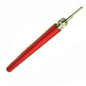
On the other shielded wire lead end, unscrew the tip of the red probe and feed the prepped other end of the shielded wire thru the hollow
red tube and this end is only needing about 1/2 an inch of the peeled out inner conductor being soldered to the probe tips connedction cavity.
Only about 1/2 an inch of the peeled outer shield is nedded to connect to about a 1/2 in length of black hook up wire.
That black hook up wire threads back into the the hollow red tube in the opposite direction that the shielded wire came in.
Terminate that black wire end with an alligator clip for ground connecting.
Screw on the probe tip and you is finished.
The other RF connector is made in the same manner , but unless youse is not well versed and " expewienced " on de' placing of a virgin
Bee Enn Cee onto a shielded cable you might just be better off in buying some audio shielded cable /or / RF cable (50 -75 -100 ohm Z . . . its
not important) with a BNC connector on one or each ends. . . . small overall diameter is imperative
The one thing of IMPORTANCE is that the overall wire diameter has to be be small enough to PASS THRU the new RF probes hollow center.
You then cut off the wire to the prior units 2-3 ft length and have a BNC connector on one end.
Build it just like you built the first probe but this time you have inserted a VEWY short leaded germanium detector diode and a 1 meg isolation
resistor between the very short length of insulated wire that was inside the shield.
The germanium diode is akin to the 1N34 or look it up in the NTE replacement semiconductors guide and you will find >10 other viable substitutes.
Prep the shielded wire, to a black hook up wire length, to route back just like the other probe made to its attached alligator grounding clip.
The one trick on this unit will be the initial finding of a small diameter of shielded cable to pass thru the probe body.
A possibility is audio video patch cables that have an BNC end, but they usually are made of/with aluminum shielding, but you can tight wind
multi turns of copper wire around it to make soldering connectivity.
Hmmmmmmm . . . . . final check . . .it seems that my initial photo of an Eico 150 was showing a BNC connector being on it, but others I now see,
ORIGINALLY were using an Amphenol microphone connector.
So if you don't change out to BNC like this othjer person did, round up one of the initial Amphenol connectors.
Now . . . . go . . . and do-it-to-it
73's de Edd

