img>
"It's a mica compression trimmer with extra fixed elements, to create an additional capacitor. While you don't see them every day, they are not uncommon. Instead of having four solder lugs on the ceramic base of the trimmer, there will be five, sometimes six."
Dennis
First up is to replace a weak rectifier tube. Don't really want to disturb this 2nd IF if I can help it.
:
:img>
:
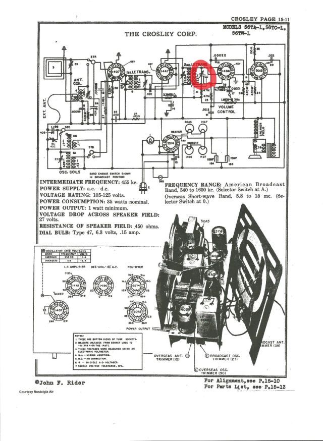
I would like to bring this thread back up because my question is related to the mica compression trimmer that Dennis helped me identify.
It is located in the 2nd IF as you can see. Now the problem is that there is low B+ (50v) throughout the radio. I get pulsating radio reception even with this low B+ with an accompanying bright dial lamp.
I replaced the rectifier tube with a NOS 35y4 today because the previous tube measured questionable on my tester. Still not much change with the new tube installed, other that a little stronger signal.
The set has been totally recapped and potential problem resistors (2) replaced. To verify that the new electrolytics were good I jumped another new ecap across connections and no change.
So now I am thinking that this mica compression trimmer that is built into the 2nd IF can, may be the issue with proper B+. Would appreciate opinions on whether this would be a high probability issue before I disassemble and remove or…..do you think it probably is something else.
All AC voltages are good in the set.
BTW, the caps that you circled are the secondary resonance-tuning caps and as such are probably unlikely to be the culprit in any fault scenario (not impossible, just unlikely). The fixed cap that is hanging off the compression cap is used to establish the "baseline" capacitance for the secondary tuned circuit, with the variable cap used to pull the circuit into precise resonance.
A couple things. Don't just jump in new electrolytic caps. Old ones need to be disconnected. They can and often are leaky lowering voltage. Pulsing sound is an indication these caps are bad.
Measure grid #1 voltage on 50A5 in relation to cathode. Grid #1 needs to be around 5 volts Negative. If zero or positive the tube will draw too much current.
By doing the above two things you should find the problem.
Norm
:Something is sucking down the B+. Most expeditious way to find out is to start at the B+ fanout and use your dikes on each branch in turn until the voltage jumps back up to nominal. Then examine the parts on the failed branch one-by-one until you find the offender. Since set has been recapped, I would look for an induced short (solder splash or errant component lead). You may be able to save a little time by first disconnecting the main B+ node and seeing if the power supply can deliver the correct B+ voltage in a no-load situation.
:
:BTW, the caps that you circled are the secondary resonance-tuning caps and as such are probably unlikely to be the culprit in any fault scenario (not impossible, just unlikely). The fixed cap that is hanging off the compression cap is used to establish the "baseline" capacitance for the secondary tuned circuit, with the variable cap used to pull the circuit into precise resonance.
:
Pulled 1 leg from speaker field and had 150vdc at cathod of rectifier so went back over all solder joints. Did not see anything shorting.
Field coil is at 442 ohms and spec is 450.
Pulled 2nd IF and rewired....it was at proper ohm values on primary and secondary. Reconnected and the set has proper AC and DC voltage.
Also Norm I checked cathod to grid on 50A5 and on VTVM I get -8vdc and on Simpson 260 I get -2.6vdc??
Electrolytics are good as checked on TO-5.
So the problem remains the pulsating or motorboating at no volume on VC and also on high volume on VC.
Beginning to think that VC may be shorting. Any other thoughts? The radio signal can be heard through the pulse so RF circuit is not an issue.
Thanks,
Scott
You might verify that all of the tube shields are present and are making electrical contact with the chassis. Omitting a shield from a glass-envelope tube, or a poorly-grounded shield, can result in the "motorboating" problem that you describe.
Some sets were designed to use steel-case tubes- if so, they do not need shields- these sets have the sockets wired to ensure that the steel case is grounded. This isn't necessarily true of sets designed to use glass tubes, so "mixing and matching" metal and glass tubes can sometimes cause problems, although not frequently enough for most people to be aware of the problem potential.