Generally the larger coil connects to the RF input, which is generally the larger or 'antenna' section of the tuning condenser, as well as the RF input section of the converter tube or 1st RF tube. This is typically the 4th grid in a pentagrid converter, or the 1st grid in a pentode RF amp. One side of the coil will connect to RF ground, which may or may not be the same as B-. If it connects directly to the RF or converter input grid, then it should be connected to the AVC bus.
The smaller coil (less turns, lower resistance) is the antenna 'primary' in most cases. Sometimes it can be a 'short-wave' winding for sets with short-wave. Sometimes it is actually a coil of much thinner wire and higher resistance, but typically it is not. It should be connected to B- through a .01 to .05 MFD capacitor, or be connected directly to B- with an isolation capacitor on the other end. The isolation capacitor must be installed either at one end or another to isolate the user and antenna from dangerous potential within the set. With AC sets this isn't necessary, as there is typically isolation between the set and the line cord provided by the power transformer, but with AC/DC sets it is necessary.
A study of most 5 and 6 tube sets will give you an idea of how the loop should connect.
The RCA 56X is a good example of a set that mimics an 'RF' input, as it has a separate converter.
The RCA 66X has an actual RF input stage (although untuned), and also has short wave.
The Zenith 5-G-500 has a pentagrid converter input.
If you search your model number in the 'Resources' section of this web site, you'll likely find a schematic for your radio, and the exact wiring method.
its a 1951 model 10D1
:
it's a D10BE, with a chassis #10D-1
According to this schematic:
http://www.nostalgiaair.org/PagesByModel/731/M0003731.pdf
which is found in the 'Resources' section of this website, your RF input is quite conventional. The smaller antenna primary is not shown in the schematic. Find the larger of the two coils and connect it as shown in the schematic. The smaller coil can be left unconnected to anything in the radio, and can then be grounded at one end and connected to a long-wire antenna at the other (25 to 100 feet). For city use, this should be quite unnecessary. The loop antenna will pick up signals across the country well on its own, if the radio is properly aligned and is functioning properly.
:
:it's a D10BE, with a chassis #10D-1
:
:According to this schematic:
:
:http://www.nostalgiaair.org/PagesByModel/731/M0003731.pdf
:
:which is found in the 'Resources' section of this website, your RF input is quite conventional. The smaller antenna primary is not shown in the schematic. Find the larger of the two coils and connect it as shown in the schematic. The smaller coil can be left unconnected to anything in the radio, and can then be grounded at one end and connected to a long-wire antenna at the other (25 to 100 feet). For city use, this should be quite unnecessary. The loop antenna will pick up signals across the country well on its own, if the radio is properly aligned and is functioning properly.
well i made a 1 by 1 and 3/4 foot frame and took 20 to 30 AWG gage wire wrapped it around it quite a bit then hooked it up to positive and negative wires from the original antenna the hook the positive up to ground all i get is a weird buzzing any pointers???
:
If you do not repair the original antenna, then you want to build a new one to the exact same dimensions and turn count as the original. If not, then you need to wind the coil for the appropriate inductance for the dimensions you choose. It would be easier to just wind to original specifications.
This is a tuned circuit, and the coil must be precisely wound or it will not tune the correct frequencies, and you will receive no signals.
:
:If you do not repair the original antenna, then you want to build a new one to the exact same dimensions and turn count as the original. If not, then you need to wind the coil for the appropriate inductance for the dimensions you choose. It would be easier to just wind to original specifications.
:
:This is a tuned circuit, and the coil must be precisely wound or it will not tune the correct frequencies, and you will receive no signals.
:
ya im havin those problems i only get 3 to 4 channels and they are super qiuet i can adjust the tuning needle on the front but stil ive grounded the negative and it doesnt help not enough chanels and there to quit any pointers on that???
Tune to a station at the low end of the dial. If the station falls where it should, skip the next step.
Make sure that the pointer stops at the stop marks on the dial at each end, or an even space from the last number.
If the station falls where it should on the dial, and the pointer falls pretty much where it should at the ends of the dial, then leave the pointer alone.
Adjust the IF transformers for maximum reception for the station at the low end of the dial. If peaking is difficult, or the reception changes when you rock the transformers, then the silver mica capacitors may need service. Otherwise continue.
If the station is not where it should be on the dial, off-tune it slightly and re-tune the IF transformers for maximum reception. Repeat until it falls where it should.
Then touch up the high end of the dial for station position and strength, preferably around 1400 KC. Use the antenna trimmer to adjust strength, and the oscillator trimmer to adjust position.
Repeat adjusting the IF transformers for the low end and the ANT and OSC trimmers for the high end until all stations fall where they should across the dial with good strength.
If the loop antenna is not restored to proper working order, do not adjust the set until it is.
:
:Tune to a station at the low end of the dial. If the station falls where it should, skip the next step.
:
:Make sure that the pointer stops at the stop marks on the dial at each end, or an even space from the last number.
:
:If the station falls where it should on the dial, and the pointer falls pretty much where it should at the ends of the dial, then leave the pointer alone.
:
:Adjust the IF transformers for maximum reception for the station at the low end of the dial. If peaking is difficult, or the reception changes when you rock the transformers, then the silver mica capacitors may need service. Otherwise continue.
:
:If the station is not where it should be on the dial, off-tune it slightly and re-tune the IF transformers for maximum reception. Repeat until it falls where it should.
:
:Then touch up the high end of the dial for station position and strength, preferably around 1400 KC. Use the antenna trimmer to adjust strength, and the oscillator trimmer to adjust position.
:
:Repeat adjusting the IF transformers for the low end and the ANT and OSC trimmers for the high end until all stations fall where they should across the dial with good strength.
:
:If the loop antenna is not restored to proper working order, do not adjust the set until it is.
:
before doing that I've tried reconnecting one disconnected wire with solder then three other wire were bent down. i don't think that matters. but its still quite i put two new tubes in it to warm it up faster but the first time i tried this antenna i put ground an the bottom hole of an outlet (ground) and it worked then i adjusted a wire plugged it back in and the thing sparked and just like that its really quiet. maybe it touched positive and after a couple seconds it blew the tube or damaged it but i don't know how to determine which tune is is. theirs one tube with a metal casing around it with a connection i cant stop wondering if thats the tube thanks for all the info i cant stop wondering if i have a bad tube and i'm in need of a tube tester so i could know for sure.
:
Repair the antenna so that it is a continuous spiral of wire forming a complete circuit of the antenna circuit, with no shorts between turns of wire.
Wire up the radio according to the schematic, which is straight forward in design. Do not alter the radio or the necessary connections to the radio.
:
:Repair the antenna so that it is a continuous spiral of wire forming a complete circuit of the antenna circuit, with no shorts between turns of wire.
:
:Wire up the radio according to the schematic, which is straight forward in design. Do not alter the radio or the necessary connections to the radio.
Now, for a preliminary check of the set after the big blow up. Standing by . . . . TECHNICAL ASIDE: 73's de Edd
Sir Seth . . . .
Tell you whuts . . . . . fill me in with some info filling facts about your set, so that I can establish enough info, in order to make a meaningful analysis.
Initially check the set of photos below, to initially confirm that this is in fact . . . . . being your ray-de-oo._Spivey.jpg)
Now, on the very last photo, notice the sloppy and lateral EXCESS application of glue on the back of the set for securing its paper label.
NEXT, is that pic looking like the actual back of the set loop antenna that is currently on the set, with THE exception that the spiral formed loop antenn coil winding is done upon the inside REAR of that back cover . . . . and thereby, we now can't see it !
Here is a photo of a Fada such that its concentrical spiral and declining loop winding procedure can be seen.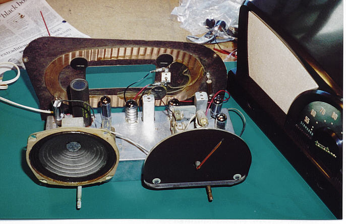
That is the type of loop antenna that I would suspicion your set to be incorporating.
Earlier in the design time frame one might have even found 1 or2 or3 or 4 or so loops of large heavy wire making up the loop antenna, such as this ole Philco 102 used.
BUT that use of but a few turns, is not providing enough inductance to match and work with your units variable tuning condenser.
It would be additionally needing to link couple into another larger coil which mates with the sets RF tuning condenser section.
This technique was mainly used in order to get the loop s--p--r--e--a--d out in physical a--r--e--a in order to get a better signal pickup footprint.
Here is that type of antenna construction,which I believe that would NOT have been applicable to YOUR sets manner of construction of ITS loop antenna.
It's being used on an -ole Peel-co set : 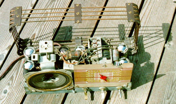
Come ye back and tells us what your situation is.
And BTW and that's VERY heavy on the BEE TEE W-YUH . . . . . don't EVER connect anything grounded to that sets chassis, or its "ground" ,as there is a 50% chance, as to which way the AC cord is inserted into the AC receptacle, that things WILL go BOOOOOOOOM . . . .with sparkee- sparkee and flashee-flashee.
.
( And I do think that you are already, a fully initiated, card carrying member of that Society)
Are the sets tubes filaments still lighting up?
Are you hearing anything from the sets speaker at max volume ?
Get a corded electric razor ( the lightest of the 2 choices) or electric drill / Dremel tool motor, turn it on, and bring it up against your present loop antenna.
Do you hear a whine of static in the speaker if the sets volume control is at max volume setting ?
Intelligentia Screw Ups
A problem cannot be solved using the same level of thinking that created it.
(In other words . . . . . if you screw it up . . . . . you can't fix it.)

:
::
::Repair the antenna so that it is a continuous spiral of wire forming a complete circuit of the antenna circuit, with no shorts between turns of wire.
::
::Wire up the radio according to the schematic, which is straight forward in design. Do not alter the radio or the necessary connections to the radio.
:
:
:
: : : : : : : : : : : :Sir Seth . . . . : : :Tell you whuts . . . . . fill me in with some info filling facts about your set, so that I can establish enough info, in order to make a meaningful analysis. : : :Initially check the set of photos below, to initially confirm that this is in fact . . . . . being your ray-de-oo. : : : : : : : : : : : : :Now, on the very last photo, notice the sloppy and lateral EXCESS application of glue on the back of the set for securing its paper label. : : :NEXT, is that pic looking like the actual back of the set loop antenna that is currently on the set, with THE exception that the spiral formed loop antenn coil winding is done upon the inside REAR of that back cover . . . . and thereby, we now can't see it ! : : :Here is a photo of a Fada such that its concentrical spiral and declining loop winding procedure can be seen. : : : : : : :That is the type of loop antenna that I would suspicion your set to be incorporating. : : : : : :Earlier in the design time frame one might have even found 1 or2 or3 or 4 or so loops of large heavy wire making up the loop antenna, such as this ole Philco 102 used. : : :BUT that use of but a few turns, is not providing enough inductance to match and work with your units variable tuning condenser. : : :It would be additionally needing to link couple into another larger coil which mates with the sets RF tuning condenser section. : : :This technique was mainly used in order to get the loop s--p--r--e--a--d out in physical a--r--e--a in order to get a better signal pickup footprint. : : :Here is that type of antenna construction,which I believe that would NOT have been applicable to YOUR sets manner of construction of ITS loop antenna. : : :It's being used on an -ole Peel-co set : : : : : : : :Come ye back and tells us what your situation is. : : :And BTW and that's VERY heavy on the BEE TEE W-YUH . . . . . don't EVER connect anything grounded to that sets chassis, or its "ground" ,as there is a 50% chance, as to which way the AC cord is inserted into the AC receptacle, that things WILL go BOOOOOOOOM . . . .with sparkee- sparkee and flashee-flashee. : : :. :( And I do think that you are already, a fully initiated, card carrying member of that Society) : : : :Now, for a preliminary check of the set after the big blow up. : : :Are the sets tubes filaments still lighting up? : : :Are you hearing anything from the sets speaker at max volume ? : : :Get a corded electric razor ( the lightest of the 2 choices) or electric drill / Dremel tool motor, turn it on, and bring it up against your present loop antenna.
: : : : : : : : : : : :> > > : : : : : : : : : : :> > > < < < : : : : : : : : : : :> > > < < < : : : : : : : : :73's de Edd : : : : : :A problem cannot be solved using the same level of thinking that created it. : : :(In other words . . . . . if you screw it up . . . . . you can't fix it.) : : : : : : : : : |
:
:
:
:
::
:i repaired the old antenna i dont think my detector tubes working i think its about dead because i hooked it back up ad now cant get anything. IM WORRIED!!!!!!!! a really cool lookin radio in the first st of picture except mines brownish so any idea. im only in my teens and new at this. so i not terribly knowledgable. if i could get a cheap cheap cheap parts radio or replacement anttena AND START FROM THEIR THAT WOULD BE GREAT ANY IDEA WARE I COULD FIND ONE. thanks. cool radios in those pics.
: