I am working on a Philco radio. I thought it was a model 60, it is not, but it is close. The 60 schematic is close but does not match this circuit. Please look at the chassis and note that there are only four capacitor blocks and not five as in the 60 schematic but does have the filter bolck as expected.
Joe has worked on this radio some time back and has added some parts that surely do not belong, a 25 ohm 10 watt resistor in the tone control circuit.
I need the correct schematic to determine what changes Joe made so I can bring the radio back to it's original state and get it working.
All help is appreciated.
Mitch


73's de Edd
|
:Hello everyone . . . . . (aka Hi yawl ). . . .,
:
:I am working on a Philco radio. I thought it was a model 60, it is not, but it is close. The 60 schematic is close but does not match this circuit. Please look at the chassis and note that there are only four capacitor blocks and not five as in the 60 schematic but does have the filter bolck as expected.
:
:Joe has worked on this radio some time back and has added some parts that surely do not belong, a 25 ohm 10 watt resistor in the tone control circuit.
:
:I need the correct schematic to determine what changes Joe made so I can bring the radio back to it's original state and get it working.
:
:All help is appreciated.
:
:Mitch
:
:
:
:
:
:
: : : :  : : : : : : : :Sir Mitch . . . . . : : :Don't we sees and counts five units on yer fotie-graf ? ? ? : : :Two at the left front at the chassis that are lined up and miving towards the center of the chassis and where the second unit ends, there is a third unit mounted at a right angle to it. : : :Then move to the very center of the chassis where there is a slightly larger unit mounted, with it being in the same longitudinal mounting plane as the first two units. Lastly, look over to the extreme other side of the chassis's right center and find yet another unit. : : : : :Supplemental Referencing: : : : : : 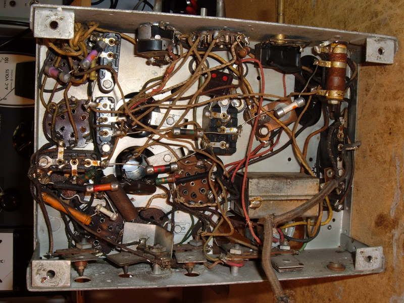 : : : : 73's de Edd : : : : : I smile . . . . . just because I have no idea of what is going on. : : : :  : : : |
:
:
:
:
::Hello everyone . . . . . (aka Hi yawl ). . . .,
::
::I am working on a Philco radio. I thought it was a model 60, it is not, but it is close. The 60 schematic is close but does not match this circuit. Please look at the chassis and note that there are only four capacitor blocks and not five as in the 60 schematic but does have the filter bolck as expected.
::
::Joe has worked on this radio some time back and has added some parts that surely do not belong, a 25 ohm 10 watt resistor in the tone control circuit.
::
::I need the correct schematic to determine what changes Joe made so I can bring the radio back to it's original state and get it working.
::
::All help is appreciated.
::
::Mitch
::
::
::
::
::
:
:
The model 60 has six block capacitors in the schematic, my chassis has a total of five. I stand corrected Sir Edd.
But, and but because of Joe i still need the correct schematic, will check the 38.
Please help until i get it right, too many changes by Joe to feel comfrontable moving forward.
Mitch
Looks pretty close.
|
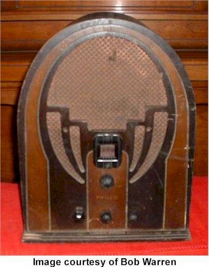
:Here's a photo (courtesy of Radio Attic) of a Philco model 38.
:
:Looks pretty close.
:
:
:
:
:Looks pretty close.
:
:
:
OK, OK, OK,
Sir Edd, your photo is exactaly my chassis. What is the model number of the radio or please post the schematic.
It is late for me and i missed your point completely.
I can see from your photo where Joe installed a resistor on my chassis that does not belong.
Await the truth.
Thank you,
Mitch
BTW, Sencore is repaired, new "FATS" tooooo skinny.
Here is the "Boto-phucket" site from whence that photo was extracted . . . . . .therewith. http://s9.photobucket.com/albums/a77/1philco/#!cpZZ5QQtppZZ16 73's de Edd I walked into a gas station today to ask the clerk for 5 dollars worth of gas. |
::Here's a photo (courtesy of Radio Attic) of a Philco model 38.
::
::Looks pretty close.
::
::
::
:OK, OK, OK,
:
:Sir Edd, your photo is exactaly my chassis. What is the model number of the radio or please post the schematic.
:
:It is late for me and i missed your point completely.
:
:I can see from your photo where Joe installed a resistor on my chassis that does not belong.
:
:Await the truth.
:
:Thank you,
:
:Mitch
:
:BTW, Sencore is repaired, new "FATS" tooooo skinny.
:
:
: : : : : : : : : : : :Sir Mitch . . . . . : : : :Here is the "Boto-phucket" site from whence that photo was extracted . . . . . .therewith. : : :(It seems a shade contrasty, let me know if you want any exploratory optimal digital enhancement of it.) : : :That unit just might be a 60B version. : : : : : :http://s9.photobucket.com/albums/a77/1philco/#!cpZZ5QQtppZZ16 : : : :Also refer to : : : :http://www.antiqueradio.org/philc08.htm : : :With its : : : : 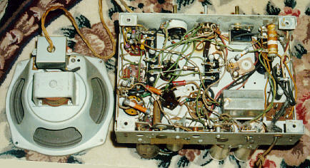 : : : : : : : 73's de Edd : : : : : :Is it all coming down to this ? . . . . . : : : :I walked into a gas station today to ask the clerk for 5 dollars worth of gas. : : :He turns, then farts, hands me a receipt and tells me to have a nice day. . : : : : : : : |
:
:
:
:
:
:
:
:
:::Here's a photo (courtesy of Radio Attic) of a Philco model 38.
:::
:::Looks pretty close.
:::
:::
:::
::OK, OK, OK,
::
::Sir Edd, your photo is exactaly my chassis. What is the model number of the radio or please post the schematic.
::
::It is late for me and i missed your point completely.
::
::I can see from your photo where Joe installed a resistor on my chassis that does not belong.
::
::Await the truth.
::
::Thank you,
::
::Mitch
::
::BTW, Sencore is repaired, new "FATS" tooooo skinny.
::
:
:
This is the radio, anyone out there have a schematic for the model 60B?
Mitch
http://www.philcoradio.com/tech/60evol.htm
:
:http://www.philcoradio.com/tech/60evol.htm
:
:
:
Thank you for the info Warren.
My model 60B is the Schematic, August 15 1934, Run #7.
It does have the wave trap and the #8 capacitor block is gone.
I changed the filter capacitors and installed a .o5 MFD capacitor in place of a resistor that had been installed for #7 in the front end.
Can someone direct me to the Philco block capacitor site so i can better identify the capacitors?
I powered the radio up and it does play now. It does receive alot of stations via reception. The problem i have is that low volume comes in very clear, as i increase the volume the sound begins to distort and is very poor sounding, return to lower volume and the sound is clear.
Any ideas on this is appreciated.
Mitch
http://www.philcorepairbench.com/bblokcap.htm
:
:http://www.philcorepairbench.com/bblokcap.htm
:
:
Hello again everyone,
I have changed all of the capacitors and have checked all of the resistors.
The radio powers up and receives all of the local and long distant stations.
The sound is still distorted from the speaker, very low volume sounds ok, as volume increases the sound begins to distort and gets worse.
The customer sent the speaker assembly to someone that reconed it for him, it looks good but was not tested with the radio. So i am using this speaker for the first time after repairing the radio.
It sounds as though it may be a bad speaker, any way to sub in another speaker or to verify if this one is good?
The field coil and voice coil are attached to the speaker housing.
Thank you,
Mitch
::
::http://www.philcorepairbench.com/bblokcap.htm
::
::
:Hello again everyone,
:I have changed all of the capacitors and have checked all of the resistors.
:
:The radio powers up and receives all of the local and long distant stations.
:
:The sound is still distorted from the speaker, very low volume sounds ok, as volume increases the sound begins to distort and gets worse.
:
:The customer sent the speaker assembly to someone that reconed it for him, it looks good but was not tested with the radio. So i am using this speaker for the first time after repairing the radio.
:
:It sounds as though it may be a bad speaker, any way to sub in another speaker or to verify if this one is good?
:
:The field coil and voice coil are attached to the speaker housing.
:
:Thank you,
:
:Mitch
:
One more note, the filter condenser bank (20) has had all of the wires cut off and is not connected, but i do not think this is causing the distortion. I will install new capacitors when i get the sound problem fixed.
:
:
I subed in a PM speaker and the results were the same. Also subed in a 41 and 75 tube, no change.
Should i be looking at the front end of this radio?
Mitch
:
:
Hello again,
I am usuig my transtor Micronta signal tracer in the AF mode to test the radio (some of you will know what this is, i have the schematic on it if needed) I also used my Heathkit IT-12 for AF. Both performed well for AF signal tracing.
On the plate of the #75 tube the volume and sound was perfect, on the plate of the #41 tube there was a lot of high buzz although the radio station was there. So, is it a component between the plate of the #75 and the plate of the #41?
Mitch
speaker system. the patch cords hot lead, tack solder it to the coupling capacitor that feeds into the AF output tube. (By lifting free, THE couplings caps lead that is going back to the 75 tube.) That sound quality, should then be the best that you will ever be hearing from that receiver, if there is being no fault within the totality of the units AF output stage circuitry . 73's de Edd
|
:With your signal tracer check the input grid on the 42 tube. see how the sound is there. This should tell you if the problem is before, or after the output tube.
:
:
: : : : : : : : : : : :Sir Mitch . . . . . : : :For quite DEFINITIVE test of the whole AF output stage, its power sourcing, its 1st grid biasing, as well as the : :speaker system. : : :Use the ~ 1V P/P audio output coming out of any one of your VCR's, DVD players or Audio CD players. : : :Connect an RCA patch cable from the AF output from either one of its R-L audio channels and take the end of : : the patch cords hot lead, tack solder it to the coupling capacitor that feeds into the AF output tube. : : (By lifting free, THE couplings caps lead that is going back to the 75 tube.) : : :The patch cables ground shell goes to Philco chassis ground. : : : :That sound quality, should then be the best that you will ever be hearing from that receiver, if there is being no : :fault within the totality of the units AF output stage circuitry . : : : : : : : 73's de Edd : : : : : : The only difference between a rut and a grave is the depth. . : : : : : : : |
:
:
::
::With your signal tracer check the input grid on the 42 tube. see how the sound is there. This should tell you if the problem is before, or after the output tube.
::
:
:
I will give it a try EDD, but for now?
But for now, with the AF signal tracer connected to the input grid #4 pin of the #41 tube it sounds crystal clear while the speaker still has distortion.
As posted earlier the speaker was sent out by the customer to be reconned. Thus i think that the field coil is ok and i am not sure if the voice coil is good or if the cone has been installed correctly.
I do have a PM speaker with a transformer connected to it from another radio, can this be something that can be subed in, and how?
Mitch
Do you have the 245 volts on the screen grid of the 42 tube? And a plate voltage of 240 volts ? Check capacitors 38 and 39. The subbed in tube 41 could also be gassy.
:Do you have the 245 volts on the screen grid of the 42 tube? And a plate voltage of 240 volts ? Check capacitors 38 and 39. The subbed in tube 41 could also be gassy.
:
:
I do have 234 volts on the screen grid, pin #3 and 205 volts on the plate, pin #2. I did sub in a audio transformer with a PM speaker to the grid and plate with the primary of the audio transformer, the distorsion was the same on both speakers.
On a cold start the radio played very clear for about ten minutes then went to distorsion at higher volume. Seems like something is breaking down after a warm up period.
The radio is crystal clear with my signal tracer connected to the grid of the #42 tube.
Comments welcome.
Mitch
:
Clifton
::Everything seems to check out good. I would suspect that 41 tube is gassy or has a fault in it. Leave it in your tube tester for an extended time. Test for shorts and leakage.
::
:
:
:
:Clifton
:
:::Everything seems to check out good. I would suspect that 41 tube is gassy or has a fault in it. Leave it in your tube tester for an extended time. Test for shorts and leakage.
:::
::
::
:
:
On a dead cold start the grid to cathode voltage is -5 VDC with clear volume, as time passes the voltage goes positive to +500 mv and there is distortion in the volume. This takes about 10 minutes. The radio is very clear at the grid with my audio signal tracer.
The #41 tube was left in the tube tester for one hour and did show a short or leakage and tested at 85% good.
Comments welcome.
Mitch
::
::Clifton
::
::::Everything seems to check out good. I would suspect that 41 tube is gassy or has a fault in it. Leave it in your tube tester for an extended time. Test for shorts and leakage.
::::
:::
:::
::
::
:On a dead cold start the grid to cathode voltage is -5 VDC with clear volume, as time passes the voltage goes positive to +500 mv and there is distortion in the volume. This takes about 10 minutes. The radio is very clear at the grid with my audio signal tracer.
:
:The #41 tube was left in the tube tester for one hour and did show a short or leakage and tested at 85% good.
:
:Comments welcome.
:
:Mitch
:
Error, tube did not show a short or leakage after one hour test.
If my problem to solve . . . . . . . 2. Any changes in the derived grid biasing source of the AF output tubes negative grid biasing from its origin at the COMMON juncture of: 3. ANY . . .heavy on the ANY . . . static DC Leakage in the .015 coupling capacitor from the AF stage to the 1st grid of the 42 tube. A tube swap out would eliminate the 42 tube question. Another test would be to take an initial reading of the negative grid bias levels at the #2 source described above and ALSO its sub grid biasing level for the 1st grid of the 75 tube at its origin at the juncture of the 32 and 235 ohm resistors.
|
:
: : : : : : : : : : : :Sir Mitch . . . . . . . : : : :If my problem to solve . . . . . . . : : :I would be considering three possibilties. : : :1. The 42 AF output tube developing the thermal onsetting of :grid emission. : : : :2. Any changes in the derived grid biasing source of the AF output tubes negative grid biasing from its origin at the COMMON juncture of: : : : : :(HV T-former center tap----negative leads of C45 and C46 electrolytic caps---high end of the series arrranged 32 and 235 ohm resistor pair of the "item 47" resistor. ) : : : : :Which gets fed up to the grid via the "item 35" half meg grid resistor. : : : :3. ANY . . .heavy on the ANY . . . static DC Leakage in the .015 coupling capacitor from the AF stage to the 1st grid of the 42 tube. : : :(Assuming that you have already replaced or FULLY tested.) : : :And that is a DC PASS through leakage test . . . not just a mere ohmmic testing. : : : :A tube swap out would eliminate the 42 tube question. : : : :Another test would be to take an initial reading of the negative grid bias levels at the #2 source described above and ALSO its sub grid biasing level for the 1st grid of the 75 tube at its origin at the juncture of the 32 and 235 ohm resistors. : : :You have also lifted the lead of the .015 coupling capacitor that was routing to the 75 tube. : : :You will thereby be without audio, but monitor the 1st grid of the 42 to see if the negative bias voltage then starts taking on its diminishing voltage drop with time related heat onsetting. : : :If it is dropping, measure back to see if the supplies were also diminishing, if not, item 35 resistor drift or grid emission onset of the 42 would be suspect. : : : : : :73's de Edd : : : : : :a ponderance . . . : : :DO INFANTS ENJOY INFANCY AS MUCH AS ADULTS ENJOY ADULTERY ? : : : : : : : : : |
:
::
I am sure we will get to the solution on this, just sorry about such a long post.
I did replace the resistors in #47 and resistor #35. I tested capacitor #33 to 500 VDC out of the circuit.
With all parts in place and on a cold start the radio come on and the grid voltage on the 42 tube measured
- 8 VDC, radio sounded very good. It took 30 minutes for the grid voltage to decrease to - 100 mV and volume distortion.
I lifted the #33 grid capacitor from the #42 tube, the radio continued to play with audio output, along with distortion. Cannot be, or could it?
This radio has been worked on in the past and has cut wires and some resistors replaced. I think there must be a path to the grid of the tube that allows it to leak and pull the grid voltage down.
Comments welcome.
Mitch
With the coupling cap between the first audio plate and output tube lifted and still having audio output to the speaker, then there must be a miswiring between the two stages. The -8 volts bias on the output tube is still low.
Clifton
::
::
::
::
::
::
::
::
::
::
::
::
::
::Sir Mitch . . . . . . .
::
::
::
::If my problem to solve . . . . . . .
::
::
::I would be considering three possibilties.
::
::
::1. The 42 AF output tube developing the thermal onsetting of
::grid emission.
::
::
::
::2. Any changes in the derived grid biasing source of the AF output tubes negative grid biasing from its origin at the COMMON juncture of:
::
::
::
::
::(HV T-former center tap----negative leads of C45 and C46 electrolytic caps---high end of the series arrranged 32 and 235 ohm resistor pair of the "item 47" resistor. )
::
::
::
::
::Which gets fed up to the grid via the "item 35" half meg grid resistor.
::
::
::
::3. ANY . . .heavy on the ANY . . . static DC Leakage in the .015 coupling capacitor from the AF stage to the 1st grid of the 42 tube.
::
::
::(Assuming that you have already replaced or FULLY tested.)
::
::
::And that is a DC PASS through leakage test . . . not just a mere ohmmic testing.
::
::
::
::A tube swap out would eliminate the 42 tube question.
::
::
::
::Another test would be to take an initial reading of the negative grid bias levels at the #2 source described above and ALSO its sub grid biasing level for the 1st grid of the 75 tube at its origin at the juncture of the 32 and 235 ohm resistors.
::
::
::You have also lifted the lead of the .015 coupling capacitor that was routing to the 75 tube.
::
::
::You will thereby be without audio, but monitor the 1st grid of the 42 to see if the negative bias voltage then starts taking on its diminishing voltage drop with time related heat onsetting.
::
::
::If it is dropping, measure back to see if the supplies were also diminishing, if not, item 35 resistor drift or grid emission onset of the 42 would be suspect.
::
::
::
::
::
::73's de Edd
::
::
::
::
::
::a ponderance . . .
::
::
::DO INFANTS ENJOY INFANCY AS MUCH AS ADULTS ENJOY ADULTERY ?
::
::
::
::
::
::
::
::
::
::
::::
:I am sure we will get to the solution on this, just sorry about such a long post.
:
:I did replace the resistors in #47 and resistor #35. I tested capacitor #33 to 500 VDC out of the circuit.
:
:With all parts in place and on a cold start the radio come on and the grid voltage on the 42 tube measured
:- 8 VDC, radio sounded very good. It took 30 minutes for the grid voltage to decrease to - 100 mV and volume distortion.
:
:I lifted the #33 grid capacitor from the #42 tube, the radio continued to play with audio output, along with distortion. Cannot be, or could it?
:
:This radio has been worked on in the past and has cut wires and some resistors replaced. I think there must be a path to the grid of the tube that allows it to leak and pull the grid voltage down.
:
:Comments welcome.
:
:Mitch
:
:
:With the coupling cap between the first audio plate and output tube lifted and still having audio output to the speaker, then there must be a miswiring between the two stages. The -8 volts bias on the output tube is still low.
:
:Clifton
:
:
:::
:::
::: ::: ::: ::: ::: ::: ::: ::: ::: ::: ::: :::Sir Mitch . . . . . . . ::: ::: ::: :::If my problem to solve . . . . . . . ::: ::: :::I would be considering three possibilties. ::: ::: :::1. The 42 AF output tube developing the thermal onsetting of :::grid emission. ::: ::: ::: :::2. Any changes in the derived grid biasing source of the AF output tubes negative grid biasing from its origin at the COMMON juncture of: ::: ::: ::: ::: :::(HV T-former center tap----negative leads of C45 and C46 electrolytic caps---high end of the series arrranged 32 and 235 ohm resistor pair of the "item 47" resistor. ) ::: ::: ::: ::: :::Which gets fed up to the grid via the "item 35" half meg grid resistor. ::: ::: ::: :::3. ANY . . .heavy on the ANY . . . static DC Leakage in the .015 coupling capacitor from the AF stage to the 1st grid of the 42 tube. ::: ::: :::(Assuming that you have already replaced or FULLY tested.) ::: ::: :::And that is a DC PASS through leakage test . . . not just a mere ohmmic testing. ::: ::: ::: :::A tube swap out would eliminate the 42 tube question. ::: ::: ::: :::Another test would be to take an initial reading of the negative grid bias levels at the #2 source described above and ALSO its sub grid biasing level for the 1st grid of the 75 tube at its origin at the juncture of the 32 and 235 ohm resistors. ::: ::: :::You have also lifted the lead of the .015 coupling capacitor that was routing to the 75 tube. ::: ::: :::You will thereby be without audio, but monitor the 1st grid of the 42 to see if the negative bias voltage then starts taking on its diminishing voltage drop with time related heat onsetting. ::: ::: :::If it is dropping, measure back to see if the supplies were also diminishing, if not, item 35 resistor drift or grid emission onset of the 42 would be suspect. ::: ::: ::: ::: ::: :::73's de Edd ::: ::: ::: ::: ::: :::a ponderance . . . ::: ::: :::DO INFANTS ENJOY INFANCY AS MUCH AS ADULTS ENJOY ADULTERY ? ::: ::: ::: ::: ::: ::: ::: ::: ::: |
:::
::::::
::I am sure we will get to the solution on this, just sorry about such a long post.
::
::I did replace the resistors in #47 and resistor #35. I tested capacitor #33 to 500 VDC out of the circuit.
::
::With all parts in place and on a cold start the radio come on and the grid voltage on the 42 tube measured
::- 8 VDC, radio sounded very good. It took 30 minutes for the grid voltage to decrease to - 100 mV and volume distortion.
::
::I lifted the #33 grid capacitor from the #42 tube, the radio continued to play with audio output, along with distortion. Cannot be, or could it?
::
::This radio has been worked on in the past and has cut wires and some resistors replaced. I think there must be a path to the grid of the tube that allows it to leak and pull the grid voltage down.
::
::Comments welcome.
::
::Mitch
::
:
:
Warren, Edd and Clifton, others that have always helped us all.
I found the problem in the radio to night and it has been playing for three hours now with great reception and the strongest volume i could expect. I have tested it with two different #41 tubes, one tube holds the grid voltage at -13 VDC and the other holds at -15 VDC. I did have a leakage from one of the bakelite block capacitors terminals that i was using as a terminal connection for the grid connection to the #41 tube, it was leaking to ground through a disconnected capacitor???? (not completely disconnected as i thought).
As you can see from the photo i drill out the rivet to cut the wire from the capacitor, did not happen this time, i used the red marked terminal as a terminal junction post for the grid connection, it was still connected to ground and shorted the grid to chassis pulling the grid voltage to zero.
I will finish the restore on the radio and feel good about giving the customer another 60 year radio to listen to.
Thank you,
Mitch
