Joe Minor K4JOE
http://www.antiqueradios.com/forums/viewtopic.php?t=100500
Schematic here:
http://www.nostalgickitscentral.com/heath/products/test.html
:Need Manual for Heathkit IP-12, 6/12 volt power supply (Battery Eliminator) Specifically the D1-D4 replacement diodes.
:Joe Minor K4JOE
:
:
:http://www.antiqueradios.com/forums/viewtopic.php?t=100500
:
:Schematic here:
:http://www.nostalgickitscentral.com/heath/products/test.html
:
:
:Here's a little more info:
http://schnittker.homeunix.net/Hobbies/Heathkit/ip12/
Bob Masse
:
:
:
::Need Manual for Heathkit IP-12, 6/12 volt power supply (Battery Eliminator) Specifically the D1-D4 replacement diodes.
::Joe Minor K4JOE
::
:
:
:::Joe Minor K4JOE
:::
::
::
:
:
::::Joe Minor K4JOE
::::
:::
:::
::
::
:
:
You will need some pretty hefty diodes. I would suggest at least 20 Amps/200V probably in a stud-mount package or TO-220 plastic. You can't use a rectifier bridge package, as this circuit switches between a full-wave center-tap and a doubler to get the two output voltage choices. Diodes are cheap, so don't under-rate. Make sure you have good heatsinking.
Rich
:::::Joe Minor K4JOE
:::::
::::
::::
:::
:::
::
::
:
:
:You will need some pretty hefty diodes. I would suggest at least 20 Amps/200V probably in a stud-mount package or TO-220 plastic. You can't use a rectifier bridge package, as this circuit switches between a full-wave center-tap and a doubler to get the two output voltage choices. Diodes are cheap, so don't under-rate. Make sure you have good heatsinking.
:Rich
:
You might try something like this:
http://www.mouser.com/ProductDetail/Vishay-Semiconductors/VS-40HFR20/?qs=sGAEpiMZZMtEwUVCuofpuAhUsscW3yWUSIYg9jNZ5b8%3d
Rich
|
:I have the schematic as listed in above 2 addresses: I need the specifications on the diodes, I would like to use the same heat sinks, therefore the replacement diode would be nice. Any more help. Thanks for replying to this request
::::Joe Minor K4JOE
::::
:::
:::
::
::
:
:
:
: : : :  : : : : : : : :Sir Joe . . . . . : : :There is the Heath schematic placed below and my additionally added (Blue) draw ups of its created switching actions. : : :Wonder if that Heathkit draftsman wuz havin’ a bad spellin’ day ? : : :Hate to have to see you put out $5’s a pop for each of those diodes Sir Rich referenced , I do believe that my well stocked “Junque Boxe” is still having some Mil Spec 1N1202 ( 12A-200 PIV) top hat studs and / or big brother 1N1124 ( 33A-200 PIV) that I could contribute to the cause. : : :Want me to check over the weekend ? : : : : : : 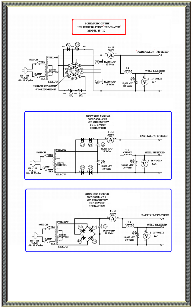 : Errata:
The 12V circuit is being on top, whle the 6V circuit is on botttom. : : : : : : : :I chose the path less traveled by . . . . . but only because I was lost. : : :  : : : |
:
:
:
:
:
:
::I have the schematic as listed in above 2 addresses: I need the specifications on the diodes, I would like to use the same heat sinks, therefore the replacement diode would be nice. Any more help. Thanks for replying to this request
:::::Joe Minor K4JOE
:::::
::::
::::
:::
:::
::
::
:
:
:since the two diodes are tapped in the middle, that is the " cathode of 1st diode---- tap----anode of 2nd diode. I am thinking one of the diodes will have to be reversed where as the metal screw in part is the cathode of the first diode and the screw in part of the second diode would have to be the anode. Any clarification would help.
Ed: you can check over the week end for the two diodes that have been mentioned, but I would like some clarification as to the 2nd reversed diode.
Thanks for all the input.
Joe- K4JOE
:
:Sir Joe . . . . .
:
:
:There is the Heath schematic placed below and my additionally added (Blue) draw ups of its created switching actions.
:
:
:Wonder if that Heathkit draftsman wuz havin’ a bad spellin’ day ?
:
:
:Hate to have to see you put out $5’s a pop for each of those diodes Sir Rich referenced , I do believe that my well stocked “Junque Boxe” is still having some Mil Spec 1N1202 ( 12A-200 PIV) top hat studs and / or big brother 1N1124 ( 33A-200 PIV) that I could contribute to the cause.
:
:
:Want me to check over the weekend ?
:
:
:
:
:
:
:
:
:
:73's de Edd
:
:
:
:
:
:
:
:I chose the path less traveled by . . . . . but only because I was lost.
:
:
:
:
:
: