If R21 is overheating cap C18 may have shorted?
http://www.nostalgiaair.org/PagesByModel/785/M0007785.pdf
Norm
:Got this G E 81 Radio that I replaced some caps about one year back and have been playing it once or twice a week and it has been working fine untill one day I turned it on and I had nothing untill I smelled smoke check to see where it was coming from the tirminal strip on the back of the chassic is heating up where the MFD 16 coectes. the schematic shows R 21 can anyone tel me what may be wrong and what kind of voltage should be there.
:
:
: If R21 is overheating cap C18 may have shorted?
:
:http://www.nostalgiaair.org/PagesByModel/785/M0007785.pdf
:
:Norm
:
::Got this G E 81 Radio that I replaced some caps about one year back and have been playing it once or twice a week and it has been working fine untill one day I turned it on and I had nothing untill I smelled smoke check to see where it was coming from the tirminal strip on the back of the chassic is heating up where the MFD 16 coectes. the schematic shows R 21 can anyone tel me what may be wrong and what kind of voltage should be there.
::
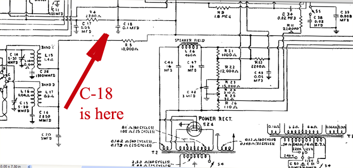
:norm can you help me find C18 I have Nostalgia only and between my eys and the heavy lines I havent found c18.
:
Looks more like it says c-48 .. but I think it's c-18
:Looks more like it says c-48 .. but I think it's c-18
:
:
Woops... that's wrong .. parts list says:
C-18 = 0.1uf @400vdc
... now where is it at.... lol...
Ahh... ok there it is.
It is shown on the print to the left of the field coil above R5 a 10k resistor.
::Looks more like it says c-48 .. but I think it's c-18
::
::
:Woops... that's wrong .. parts list says:
:C-18 = 0.1uf @400vdc
:... now where is it at.... lol...
:Ahh... ok there it is.
:It is shown on the print to the left of the field coil above R5 a 10k resistor.
:Peter I am still not sure where it is would you be kind enough to let me send you a picture and you could mark the c18. my e-mail is decanup@bigriver.net thanks for helping me. david
:::Looks more like it says c-48 .. but I think it's c-18
:::
:::
::Woops... that's wrong .. parts list says:
::C-18 = 0.1uf @400vdc
::... now where is it at.... lol...
::Ahh... ok there it is.
::It is shown on the print to the left of the field coil above R5 a 10k resistor.
::Peter I am still not sure where it is would you be kind enough to let me send you a picture and you could mark the c18. my e-mail is decanup@bigriver.net thanks for helping me. david
:
:
Sure:
Peter AT Pbpix dot com
to the second RED square where there is a terminal strip lug centered within that square, that point feeds sub B+ to several branchoffs. chassis' parts layout .
|
:Does this help?
:
:
:
: : : :  :YOU GUY,S ARE GREAT AND I THANK YOU VERY MUCH DAVID : : : : : : :Sir David. . . . . : : :Hmmmmmmm . . .? . . . . looks like the "Ballz-ster" seems to have merely taken the path far too simple. : : :Now, in referring to the photographic mark up placed below . . . : : :The bottom RED square is the problem area of the hotsy totsy R18 resistor, with a connective wire (blue-black ? ) that moves straight upward, : : to the second RED square where there is a terminal strip lug centered within that square, that point feeds sub B+ to several branchoffs. : : :We are interested to that orangish appearing paper cap. . . . BUT ITS NOT being a newer, certified Orange drop . . . capacitor. : : : I have it marked up with a smaller BLUE square, both on the physical photo as well as its position on the adjunct pictorial schematic of the : : chassis' parts layout . : : :Its opposite, outer foil, banded lead is being grounded at the 2nd IF transformer at the YELLOW box markup. : : :Circuitwise . . . . that cap is the first most likely candidate for your described problem. :Tech Referencing: : : : : : : :  : : : : : : : : : : :73's de Edd : : : : : :I do some of my best fishing whenever it starts to rain . . . HOW's That ? . . . by moving over under a bridge. : : :The fish then keep crowding in under it, to get out of the wet. : : :  : : : |
:
:
:
:
:
:
::Does this help?
::
::
:
:
::
:: :: :: :: ::YOU GUY,S ARE GREAT AND I THANK YOU VERY MUCH DAVID ::well I thought with you all helping I had found the problem when I found the cap was not soldered to the tube pin I went ahead and replaced the cap and checked and found I still have the problem so I am back to square one. any more Ideas. :: :: :: :: :: ::Sir David. . . . . :: :: ::Hmmmmmmm . . .? . . . . looks like the "Ballz-ster" seems to have merely taken the path far too simple. :: :: ::Now, in referring to the photographic mark up placed below . . . :: :: ::The bottom RED square is the problem area of the hotsy totsy R18 resistor, with a connective wire (blue-black ? ) that moves straight upward, :: :: to the second RED square where there is a terminal strip lug centered within that square, that point feeds sub B+ to several branchoffs. :: :: ::We are interested to that orangish appearing paper cap. . . . BUT ITS NOT being a newer, certified Orange drop . . . capacitor. :: :: :: I have it marked up with a smaller BLUE square, both on the physical photo as well as its position on the adjunct pictorial schematic of the :: :: chassis' parts layout . :: :: ::Its opposite, outer foil, banded lead is being grounded at the 2nd IF transformer at the YELLOW box markup. :: :: ::Circuitwise . . . . that cap is the first most likely candidate for your described problem. ::Tech Referencing: :: :: :: :: :: :: :: :: :: :: :: :: :: :: :: :: :: ::73's de Edd :: :: :: :: :: ::I do some of my best fishing whenever it starts to rain . . . HOW's That ? . . . by moving over under a bridge. :: :: ::The fish then keep crowding in under it, to get out of the wet. :: :: :: :: :: :: |
::
::
::
::
::
::
:::Does this help?
:::
:::
::
::
:
:
I personally would make my next test a cold set, power off, ohmming out evaluation of that POWER STRIP Candohm wirewound resistor with its six different sections. |
:::
:::
:::
:::
:::
:::
:::YOU GUY,S ARE GREAT AND I THANK YOU VERY MUCH DAVID
:::well I thought with you all helping I had found the problem when I found the cap was not soldered to the tube pin I went ahead and replaced the cap and checked and found I still have the problem so I am back to square one. any more Ideas.
:::
:::
:::
:::
:::
:::Sir David. . . . .
:::
:::
:::Hmmmmmmm . . .? . . . . looks like the "Ballz-ster" seems to have merely taken the path far too simple.
:::
:::
:::Now, in referring to the photographic mark up placed below . . .
:::
:::
:::The bottom RED square is the problem area of the hotsy totsy R18 resistor, with a connective wire (blue-black ? ) that moves straight upward,
:::
::: to the second RED square where there is a terminal strip lug centered within that square, that point feeds sub B+ to several branchoffs.
:::
:::
:::We are interested to that orangish appearing paper cap. . . . BUT ITS NOT being a newer, certified Orange drop . . . capacitor.
:::
:::
::: I have it marked up with a smaller BLUE square, both on the physical photo as well as its position on the adjunct pictorial schematic of the
:::
::: chassis' parts layout .
:::
:::
:::Its opposite, outer foil, banded lead is being grounded at the 2nd IF transformer at the YELLOW box markup.
:::
:::
:::Circuitwise . . . . that cap is the first most likely candidate for your described problem.
:::Tech Referencing:
:::
:::
:::
:::
:::
:::
:::
:::
:::
:::
:::
:::
:::
:::
:::
:::
:::
:::73's de Edd
:::
:::
:::
:::
:::
:::I do some of my best fishing whenever it starts to rain . . . HOW's That ? . . . by moving over under a bridge.
:::
:::
:::The fish then keep crowding in under it, to get out of the wet.
:::
:::
:::
:::
:::
:::
:::
:::
:::
:::
:::
:::
::::Does this help?
::::
::::
:::
:::
::
::
:
:
:
: :Edd I am not sure I can go any futher this is a little beyond my knowlledge. : : : : : : : : : :Sir David . . . . . : : :The best laid plans of mice and men . . . . . . : : : :I personally would make my next test a cold set, power off, ohmming out evaluation of that POWER STRIP Candohm wirewound resistor with its six different sections. : : :One or more sections may be at fault . . . . some sections really dissipate some power, hence its additional use of heatsinking by its being strapped to the chassis proper . . . to disperse the heat outwardly and away. : : :Check and see if its ohmming out OK on its series arrangement of its sections of : : : : 110 ohms----30 ohms---200 ohms---15,000 ohms---12,000 ohms----1000 ohms. : : :Lastly THEN power up ye olde set and pass on to us, the voltages read on each of those 7 resistor nodes inter connections, ( one of which will be chassis ground ) . : : : : : :73's de Edd : : : : : :A man should be greater than some of his parts. : : : : : : : : |
:
:
:
:
::::
::::
:::: :::: :::: :::: ::::YOU GUY,S ARE GREAT AND I THANK YOU VERY MUCH DAVID ::::well I thought with you all helping I had found the problem when I found the cap was not soldered to the tube pin I went ahead and replaced the cap and checked and found I still have the problem so I am back to square one. any more Ideas. :::: :::: :::: :::: :::: ::::Sir David. . . . . :::: :::: ::::Hmmmmmmm . . .? . . . . looks like the "Ballz-ster" seems to have merely taken the path far too simple. :::: :::: ::::Now, in referring to the photographic mark up placed below . . . :::: :::: ::::The bottom RED square is the problem area of the hotsy totsy R18 resistor, with a connective wire (blue-black ? ) that moves straight upward, :::: :::: to the second RED square where there is a terminal strip lug centered within that square, that point feeds sub B+ to several branchoffs. :::: :::: ::::We are interested to that orangish appearing paper cap. . . . BUT ITS NOT being a newer, certified Orange drop . . . capacitor. :::: :::: :::: I have it marked up with a smaller BLUE square, both on the physical photo as well as its position on the adjunct pictorial schematic of the :::: :::: chassis' parts layout . :::: :::: ::::Its opposite, outer foil, banded lead is being grounded at the 2nd IF transformer at the YELLOW box markup. :::: :::: ::::Circuitwise . . . . that cap is the first most likely candidate for your described problem. ::::Tech Referencing: :::: :::: :::: :::: :::: :::: :::: :::: :::: :::: :::: :::: :::: :::: :::: :::: :::: ::::73's de Edd :::: :::: :::: :::: :::: ::::I do some of my best fishing whenever it starts to rain . . . HOW's That ? . . . by moving over under a bridge. :::: :::: ::::The fish then keep crowding in under it, to get out of the wet. :::: :::: :::: :::: :::: :::: |
::::
::::
::::
::::
::::
::::
:::::Does this help?
:::::
:::::
::::
::::
:::
:::
::
::
:
:
What our wise and powerful friend sir Edd is referring to is simply a multiple value power resistor in a single package that is chassis mounted. It is basically flat and resembles a terminal strip. These were used @ the 30's, but later phased out.
But, you need a multi-meter to measure ohms (with radio unplugged), and voltage (radio powered) at each terminal with reference to chassis gnd. If you are not comfortable with high voltage, do not proceed with the powered test. Good luck....Dave
::Edd I am not sure I can go any futher this is a little beyond my knowlledge.
::
::
::
::
::
::
::
::
::
::Sir David . . . . .
::
::
::The best laid plans of mice and men . . . . . .
::
::
::
::I personally would make my next test a cold set, power off, ohmming out evaluation of that POWER STRIP Candohm wirewound resistor with its six different sections.
::
::
::One or more sections may be at fault . . . . some sections really dissipate some power, hence its additional use of heatsinking by its being strapped to the chassis proper . . . to disperse the heat outwardly and away.
::
::
::Check and see if its ohmming out OK on its series arrangement of its sections of :
::
::
:: 110 ohms----30 ohms---200 ohms---15,000 ohms---12,000 ohms----1000 ohms.
::
::
::Lastly THEN power up ye olde set and pass on to us, the voltages read on each of those 7 resistor nodes inter connections, ( one of which will be chassis ground )
:
:
:
:What our wise and powerful friend sir Edd is referring to is simply a multiple value power resistor in a single package that is chassis mounted. It is basically flat and resembles a terminal strip. These were used @ the 30's, but later phased out.
:
:But, you need a multi-meter to measure ohms (with radio unplugged), and voltage (radio powered) at each terminal with reference to chassis gnd. If you are not comfortable with high voltage, do not proceed with the powered test. Good luck....Dave
:
:::Edd I am not sure I can go any futher this is a little beyond my knowlledge.
:::
:::
:::
:::
:::
:::
:::
:::
:::
:::Sir David . . . . .
:::
:::
:::The best laid plans of mice and men . . . . . .
:::
:::
:::
:::I personally would make my next test a cold set, power off, ohmming out evaluation of that POWER STRIP Candohm wirewound resistor with its six different sections.
:::
:::
:::One or more sections may be at fault . . . . some sections really dissipate some power, hence its additional use of heatsinking by its being strapped to the chassis proper . . . to disperse the heat outwardly and away.
:::
:::
:::Check and see if its ohmming out OK on its series arrangement of its sections of :
:::
:::
::: 110 ohms----30 ohms---200 ohms---15,000 ohms---12,000 ohms----1000 ohms.
:::
:::
:::Lastly THEN power up ye olde set and pass on to us, the voltages read on each of those 7 resistor nodes inter connections, ( one of which will be chassis ground )
::
::I WILL TAKE ANOTHER LOOK AT IT AS SOON I GET A CHANCE AND GET BACK TO YOU. THANKS DAVID
:
:
:
:What our wise and powerful friend sir Edd is referring to is simply a multiple value power resistor in a single package that is chassis mounted. It is basically flat and resembles a terminal strip. These were used @ the 30's, but later phased out.
:
:But, you need a multi-meter to measure ohms (with radio unplugged), and voltage (radio powered) at each terminal with reference to chassis gnd. If you are not comfortable with high voltage, do not proceed with the powered test. Good luck....Dave
:
:::Edd I am not sure I can go any futher this is a little beyond my knowlledge.
:::
:::
:::
:::
:::
:::
:::
:::
:::
:::Sir David . . . . .
:::
:::
:::The best laid plans of mice and men . . . . . .
:::
:::
:::
:::I personally would make my next test a cold set, power off, ohmming out evaluation of that POWER STRIP Candohm wirewound resistor with its six different sections.
:::
:::
:::One or more sections may be at fault . . . . some sections really dissipate some power, hence its additional use of heatsinking by its being strapped to the chassis proper . . . to disperse the heat outwardly and away.
:::
:::
:::Check and see if its ohmming out OK on its series arrangement of its sections of :
:::
:::
::: 110 ohms----30 ohms---200 ohms---15,000 ohms---12,000 ohms----1000 ohms.
:::
:::
:::Lastly THEN power up ye olde set and pass on to us, the voltages read on each of those 7 resistor nodes inter connections, ( one of which will be chassis ground )
::
::
:
:
::
::What our wise and powerful friend sir Edd is referring to is simply a multiple value power resistor in a single package that is chassis mounted. It is basically flat and resembles a terminal strip. These were used @ the 30's, but later phased out.
::
::But, you need a multi-meter to measure ohms (with radio unplugged), and voltage (radio powered) at each terminal with reference to chassis gnd. If you are not comfortable with high voltage, do not proceed with the powered test. Good luck....Dave
::
::::Edd I am not sure I can go any futher this is a little beyond my knowlledge.
::::
::::
::::
::::
::::
::::
::::
::::
::::
::::Sir David . . . . .
::::
::::
::::The best laid plans of mice and men . . . . . .
::::
::::
::::
::::I personally would make my next test a cold set, power off, ohmming out evaluation of that POWER STRIP Candohm wirewound resistor with its six different sections.
::::
::::
::::One or more sections may be at fault . . . . some sections really dissipate some power, hence its additional use of heatsinking by its being strapped to the chassis proper . . . to disperse the heat outwardly and away.
::::
::::
::::Check and see if its ohmming out OK on its series arrangement of its sections of :
::::
::::
:::: 110 ohms----30 ohms---200 ohms---15,000 ohms---12,000 ohms----1000 ohms.
::::
::::
::::Lastly THEN power up ye olde set and pass on to us, the voltages read on each of those 7 resistor nodes inter connections, ( one of which will be chassis ground )
:::
:::dave I checked and my ohm meter says the reading starts at r21 1.223 ,163.8 ,2.527 ,2.121.9 ,.5 ,41.3 ,163.4 these are not exact what you gave me what do you think< david
::
::
:
:
photo of that Gentile Eclectic 81 series of chassicateur . . . . . " Red Riders' " ( and Little Beaver says . . . " Me heap gus dusted ! " ) physical pictorial now placed at the very bottom of the page. certainly left room for some numerical ambiguity. sections, and then give back that info . PICTORIAL REFERENCING: All syllogisms have three parts; therefore, this is NOT a syllogism. |
:::David,
:::
:::What our wise and powerful friend sir Edd is referring to is simply a multiple value power resistor in a single package that is chassis mounted. It is basically flat and resembles a terminal strip. These were used @ the 30's, but later phased out.
:::
:::But, you need a multi-meter to measure ohms (with radio unplugged), and voltage (radio powered) at each terminal with reference to chassis gnd. If you are not comfortable with high voltage, do not proceed with the powered test. Good luck....Dave
Hmmmmmmmmm now would that be "other" Dave Ffffffffff ?
:::
:::::Edd I am not sure I can go any futher this is a little beyond my knowlledge.
:::::
:::::
:::::
:::::
:::::
:::::
:::::
:::::
:::::
:::::Sir David . . . . .
:::::
:::::
:::::The best laid plans of mice and men . . . . . .
:::::
:::::
:::::
:::::I personally would make my next test a cold set, power off, ohmming out evaluation of that POWER STRIP Candohm wirewound resistor with its six different sections.
:::::
:::::
:::::One or more sections may be at fault . . . . some sections really dissipate some power, hence its additional use of heatsinking by its being strapped to the chassis proper . . . to disperse the heat outwardly and away.
:::::
:::::
:::::Check and see if its ohmming out OK on its series arrangement of its sections of :
:::::
:::::
::::: 110 ohms----30 ohms---200 ohms---15,000 ohms---12,000 ohms----1000 ohms.
:::::
:::::
:::::Lastly THEN power up ye olde set and pass on to us, the voltages read on each of those 7 resistor nodes inter connections, ( one of which will be chassis ground )
::::
::::dave I checked and my ohm meter says the reading starts at r21 1.223 ,163.8 ,2.527 ,2.121.9 ,.5 ,41.3 ,163.4 these are not exact what you gave me what do you think< david
:::
:::
::
::
:
:
:
:
: : : : : : : : : : : :Sir Dave . . . . . : : :Edd I am not sure I can go any futher this is a little beyond my knowlledge. : : :With your fully adequate comebacks . . .to date . . . . you have yet to make me believe that statement. : : :Now, in looking at the measured ohmmic readings that you came back with, and my consulting of my prior provided : :photo of that Gentile Eclectic 81 series of chassicateur . . . . . : : :AND the possibility that your mere fallacy is relating the potentially cryptic schematic to the real world. :I have now generated yet another mark-up photo of the underchassis. : : :This , being with the full designation of the Candohm /or/ Muter power strip wire wound resistor, along with the : :" Red Riders' " ( and Little Beaver says . . . " Me heap gus dusted ! " ) physical pictorial now placed at the very bottom of the page. : : :That measured .5 ohms of meter lead resistance 'soitanly identifies the chassis grounded terminal. : : :Your measuring all of them reference to ground . . INITIALLY . . suggests a fallacy around the R24 section . : : :HOWEVER, with your throwing at me, that " 2(Comma ?)1 2 1 (Decimal)9 " . . . . for your fourth ohms reading, : :certainly left room for some numerical ambiguity. : : :Now, at the other opposite end of the string, the 163.4 ohms (hi +) and 41.3 ohms (hi+) "sort" of equate. : : :Sooooooo., lets use the mark-up info and go back and ohmically read between EACH of the individual resistor : : sections, and then give back that info . : : :(That would be reading from A-B . . . B-C . . . C-D . . .D-E . . .E-F . . .F-G.) : : :Standing by . . . . . : : : : : :PICTORIAL REFERENCING: : : : : : :  : : : : : : : : : : : : : : :73's de Edd : : : : : : :All syllogisms have three parts; therefore, this is NOT a syllogism. : : : : : : : : |
:
:
:
::::David,
::::
::::What our wise and powerful friend sir Edd is referring to is simply a multiple value power resistor in a single package that is chassis mounted. It is basically flat and resembles a terminal strip. These were used @ the 30's, but later phased out.
::::
::::But, you need a multi-meter to measure ohms (with radio unplugged), and voltage (radio powered) at each terminal with reference to chassis gnd. If you are not comfortable with high voltage, do not proceed with the powered test. Good luck....Dave
:Hmmmmmmmmm now would that be "other" Dave Ffffffffff ?
::::
::::::Edd I am not sure I can go any futher this is a little beyond my knowlledge.
::::::
::::::
::::::
::::::
::::::
::::::
::::::
::::::
::::::
::::::Sir David . . . . .
::::::
::::::
::::::The best laid plans of mice and men . . . . . .
::::::
::::::
::::::
::::::I personally would make my next test a cold set, power off, ohmming out evaluation of that POWER STRIP Candohm wirewound resistor with its six different sections.
::::::
::::::
::::::One or more sections may be at fault . . . . some sections really dissipate some power, hence its additional use of heatsinking by its being strapped to the chassis proper . . . to disperse the heat outwardly and away.
::::::
::::::
::::::Check and see if its ohmming out OK on its series arrangement of its sections of :
::::::
::::::
:::::: 110 ohms----30 ohms---200 ohms---15,000 ohms---12,000 ohms----1000 ohms.
::::::
::::::
::::::Lastly THEN power up ye olde set and pass on to us, the voltages read on each of those 7 resistor nodes inter connections, ( one of which will be chassis ground )
:::::
:::::dave I checked and my ohm meter says the reading starts at r21 1.223 ,163.8 ,2.527 ,2.121.9 ,.5 ,41.3 ,163.4 these are not exact what you gave me what do you think< david
::::Edd I got to check the radio again and I found the smoke is comming from R22 and not R21 as I said at first, now I made a check with it hot where the smoke is comming from the resistor I took a pair of plires and moved it a little and the smoke stoped and the radio would play mabe the problem is in the resistor strip how can I repair that or bypass it with that terimal there is a resister conected there. david
::::
:::
:::
::
::
:
:
::
::
:: :: :: :: :: :: :: :: :: :: :: ::Sir Dave . . . . . :: :: ::Edd I am not sure I can go any futher this is a little beyond my knowlledge. :: :: ::With your fully adequate comebacks . . .to date . . . . you have yet to make me believe that statement. :: :: ::Now, in looking at the measured ohmmic readings that you came back with, and my consulting of my prior provided :: ::photo of that Gentile Eclectic 81 series of chassicateur . . . . . :: :: ::AND the possibility that your mere fallacy is relating the potentially cryptic schematic to the real world. ::I have now generated yet another mark-up photo of the underchassis. :: :: ::This , being with the full designation of the Candohm /or/ Muter power strip wire wound resistor, along with the :: ::" Red Riders' " ( and Little Beaver says . . . " Me heap gus dusted ! " ) physical pictorial now placed at the very bottom of the page. :: :: ::That measured .5 ohms of meter lead resistance 'soitanly identifies the chassis grounded terminal. :: :: ::Your measuring all of them reference to ground . . INITIALLY . . suggests a fallacy around the R24 section . :: :: ::HOWEVER, with your throwing at me, that " 2(Comma ?)1 2 1 (Decimal)9 " . . . . for your fourth ohms reading, :: ::certainly left room for some numerical ambiguity. :: :: ::Now, at the other opposite end of the string, the 163.4 ohms (hi +) and 41.3 ohms (hi+) "sort" of equate. :: :: ::Sooooooo., lets use the mark-up info and go back and ohmically read between EACH of the individual resistor :: :: sections, and then give back that info . :: :: ::(That would be reading from A-B . . . B-C . . . C-D . . .D-E . . .E-F . . .F-G.) :: :: ::Standing by . . . . . :: :: :: :: :: ::PICTORIAL REFERENCING: :: :: :: :: :: :: :: :: :: :: :: :: :: :: :: :: :: :: :: :: ::73's de Edd :: :: :: :: :: :: ::All syllogisms have three parts; therefore, this is NOT a syllogism. :: :: :: :: :: :: :: :: |
::
::
::
:::::David,
:::::
:::::What our wise and powerful friend sir Edd is referring to is simply a multiple value power resistor in a single package that is chassis mounted. It is basically flat and resembles a terminal strip. These were used @ the 30's, but later phased out.
:::::
:::::But, you need a multi-meter to measure ohms (with radio unplugged), and voltage (radio powered) at each terminal with reference to chassis gnd. If you are not comfortable with high voltage, do not proceed with the powered test. Good luck....Dave
::Hmmmmmmmmm now would that be "other" Dave Ffffffffff ?
:::::
:::::::Edd I am not sure I can go any futher this is a little beyond my knowlledge.
:::::::
:::::::
:::::::
:::::::
:::::::
:::::::
:::::::
:::::::
:::::::
:::::::Sir David . . . . .
:::::::
:::::::
:::::::The best laid plans of mice and men . . . . . .
:::::::
:::::::
:::::::
:::::::I personally would make my next test a cold set, power off, ohmming out evaluation of that POWER STRIP Candohm wirewound resistor with its six different sections.
:::::::
:::::::
:::::::One or more sections may be at fault . . . . some sections really dissipate some power, hence its additional use of heatsinking by its being strapped to the chassis proper . . . to disperse the heat outwardly and away.
:::::::
:::::::
:::::::Check and see if its ohmming out OK on its series arrangement of its sections of :
:::::::
:::::::
::::::: 110 ohms----30 ohms---200 ohms---15,000 ohms---12,000 ohms----1000 ohms.
:::::::
:::::::
:::::::Lastly THEN power up ye olde set and pass on to us, the voltages read on each of those 7 resistor nodes inter connections, ( one of which will be chassis ground )
::::::
::::::dave I checked and my ohm meter says the reading starts at r21 1.223 ,163.8 ,2.527 ,2.121.9 ,.5 ,41.3 ,163.4 these are not exact what you gave me what do you think< david
:::::Edd I got to check the radio again and I found the smoke is comming from R22 and not R21 as I said at first, now I made a check with it hot where the smoke is comming from the resistor I took a pair of plires and moved it a little and the smoke stoped and the radio would play mabe the problem is in the resistor strip how can I repair that or bypass it with that terimal there is a resister conected there. david
:::::
::::
::::
:::
:::I feel like I may haave wore you guy,s out but I need to know where I can go from here,is the teriminal strip replaceable or repairable
david
::
::
:
:
Edd I got to check the radio again and I found the smoke is comming from R22 and not R21 as I said at first, now I made a check with it hot where the smoke is comming from the resistor I took a pair of plires and moved it a little and the smoke stoped and the radio would play mabe the problem is in the resistor strip how can I repair that or bypass it with that terimal there is a resister conected there. CERAMIC BLOCK RESISTOR: We can get you on the flight path . . . electronically speaking . . . and you might even be more adept with the mechanical aspect of pulling that resistor, and replacing with a string of new resistors . (After POSITIVELY tagging its EVERY connection wire . .or part.) Asking dumb questions is easier than correcting dumb mistakes.
Sir Dave . . . . .
I feel like I may haave wore you guy,s out but I need to know where I can go from here,is the teriminal strip replaceable or repairable.
Not taxable at all, on my end . . .I was just away for the weekend.
Now I have no idea as to the degree of “restoration” that the set is already in.
As you can see our “picture chassis” has had no paper capacitors replaced.
Somehow I just seem to sense that your chassis is also “au original” condition.
As for your problem section of the power strip resistor, if you were able to see its internal construction,
expect this:
There is a long rectangular insulator in the center of the power resistor that has nichrome wire close wound upon it using VERY close spacing, but not touching between the adjacent turns.
They transition between nichrome wire gauges for the different sections, with larger gauge being used for one ends R26-R25 and R24 sections.
Then there is transition to VERY fine wire for the R23 and R22 sections and finally the use of intermediate gauge sized nichrome wire for the end R21 section.
Look at the exploded pic of a TWO section unit just below and you can see the manner of construction of a Candohm power strip resistor :
Initially one sees a peeling off of the metal wrap around housing of the unit and its holes that the terminal lugs pass thru at the top left corner.
Then there is the metal strip off to the right that has the mounting screw holes at both ends for the 6-32 mounting screws.
The blue-black center component is the side of the terminal connector strip that presses against the wire wound insulator form, one can not see the familiar terminals on its opposite side, which protrude thru the surround metal strip housing.
Located center bottom . . .vertically . . . is THE initially mentioned insulated form with the fine nichrome wire wound around it.
Contact action between the point on the nichrome wound form and its contact strip is dependent upon the press crimping action in the assembly time of installing the resistor’s outer metal wrap.
Additionally there is the placement of an insulated wrap around the nichrome form and inside the housing for providing separative insulation, usually in the manner of making a longitudinal wrap using heavy fish paper / light cardboard.
This construction leaves fault in the respect of just depending upon mere pressure contact between the nichrome wire and the terminal strip, or with time, the heating of the isolative insulated surround and its potential charring and then progressing on to carbonification and finally, making a conductive flow to the outer cases metal ground surround. ( ‘moke . . .'moke . . .I smells ‘MOKE ! ).
Now you say . . . .
I need to know where I can go from here,is the teriminal strip replaceable or repairable
david
Now, with me having just mentioned the fallacies of that “ ’MOKIN” power strip section, along with your pliers pressing, in having potentially nudged that terminal into making (temporary) contact with its nichrome contact area again.
I can rightfully only see long time reliability with the removal of that power strip resistor in its entirety and the replacement of it with an . . .end to end . . .mounting of a string of Ceramic block or “DALE” style of power resistors, then you will finally be trouble free.
DALE RESISTOR CASES . . . strung together: 

You get a strip of 1/8 up to ¼ in thick aluminum stock about the same dimensions as the prior “footprint” of the old power resistor sizing, or potentially even a bit wider and longer, such as aside components will permit.
Then you use 4/40 hardware to mount the ears of the spaced apart “DALE “ units to the alum stock or use terminals if alternatively using ceramic block resistors.
Its then a re-connecting of the pulled wires to the paired together terminals of the replaced power resistor sections .
What say you . . . . can handle it ?
73's de Edd
:::
:::
:::
:::
:::
:::
:::
:::
:::
:::
:::
:::
:::
:::
:::Sir Dave . . . . .
:::
:::
:::Edd I am not sure I can go any futher this is a little beyond my knowlledge.
:::
:::
:::With your fully adequate comebacks . . .to date . . . . you have yet to make me believe that statement.
:::
:::
:::Now, in looking at the measured ohmmic readings that you came back with, and my consulting of my prior provided
:::
:::photo of that Gentile Eclectic 81 series of chassicateur . . . . .
:::
:::
:::AND the possibility that your mere fallacy is relating the potentially cryptic schematic to the real world.
:::I have now generated yet another mark-up photo of the underchassis.
:::
:::
:::This , being with the full designation of the Candohm /or/ Muter power strip wire wound resistor, along with the
:::
:::" Red Riders' " ( and Little Beaver says . . . " Me heap gus dusted ! " ) physical pictorial now placed at the very bottom of the page.
:::
:::
:::That measured .5 ohms of meter lead resistance 'soitanly identifies the chassis grounded terminal.
:::
:::
:::Your measuring all of them reference to ground . . INITIALLY . . suggests a fallacy around the R24 section .
:::
:::
:::HOWEVER, with your throwing at me, that " 2(Comma ?)1 2 1 (Decimal)9 " . . . . for your fourth ohms reading,
:::
:::certainly left room for some numerical ambiguity.
:::
:::
:::Now, at the other opposite end of the string, the 163.4 ohms (hi +) and 41.3 ohms (hi+) "sort" of equate.
:::
:::
:::Sooooooo., lets use the mark-up info and go back and ohmically read between EACH of the individual resistor
:::
::: sections, and then give back that info .
:::
:::
:::(That would be reading from A-B . . . B-C . . . C-D . . .D-E . . .E-F . . .F-G.)
:::
:::
:::Standing by . . . . .
:::
:::
:::
:::
:::
:::PICTORIAL REFERENCING:
:::
:::
:::
:::
:::
:::
:::
:::
:::
:::
:::
:::
:::
:::
:::
:::
:::
:::
:::
:::
:::73's de Edd
:::
:::
:::
:::
:::
:::
:::All syllogisms have three parts; therefore, this is NOT a syllogism.
:::
:::
:::
:::
:::
:::
:::
:::
:::
:::
:::
::::::David,
::::::
::::::What our wise and powerful friend sir Edd is referring to is simply a multiple value power resistor in a single package that is chassis mounted. It is basically flat and resembles a terminal strip. These were used @ the 30's, but later phased out.
::::::
::::::But, you need a multi-meter to measure ohms (with radio unplugged), and voltage (radio powered) at each terminal with reference to chassis gnd. If you are not comfortable with high voltage, do not proceed with the powered test. Good luck....Dave
:::Hmmmmmmmmm now would that be "other" Dave Ffffffffff ?
::::::
::::::::Edd I am not sure I can go any futher this is a little beyond my knowlledge.
::::::::
::::::::
::::::::
::::::::
::::::::
::::::::
::::::::
::::::::
::::::::
::::::::Sir David . . . . .
::::::::
::::::::
::::::::The best laid plans of mice and men . . . . . .
::::::::
::::::::
::::::::
::::::::I personally would make my next test a cold set, power off, ohmming out evaluation of that POWER STRIP Candohm wirewound resistor with its six different sections.
::::::::
::::::::
::::::::One or more sections may be at fault . . . . some sections really dissipate some power, hence its additional use of heatsinking by its being strapped to the chassis proper . . . to disperse the heat outwardly and away.
::::::::
::::::::
::::::::Check and see if its ohmming out OK on its series arrangement of its sections of :
::::::::
::::::::
:::::::: 110 ohms----30 ohms---200 ohms---15,000 ohms---12,000 ohms----1000 ohms.
::::::::
::::::::
::::::::Lastly THEN power up ye olde set and pass on to us, the voltages read on each of those 7 resistor nodes inter connections, ( one of which will be chassis ground )
:::::::
:::::::dave I checked and my ohm meter says the reading starts at r21 1.223 ,163.8 ,2.527 ,2.121.9 ,.5 ,41.3 ,163.4 these are not exact what you gave me what do you think< david
::::::Edd I got to check the radio again and I found the smoke is comming from R22 and not R21 as I said at first, now I made a check with it hot where the smoke is comming from the resistor I took a pair of plires and moved it a little and the smoke stoped and the radio would play mabe the problem is in the resistor strip how can I repair that or bypass it with that terimal there is a resister conected there. david
::::::
:::::
:::::
::::
::::I feel like I may haave wore you guy,s out but I need to know where I can go from here,is the teriminal strip replaceable or repairable
:david
:::
:::
::
::
:
:
:
:
:
:
:
: : : : : : : : : : : :Sir Dave . . . . . : : : :I feel like I may haave wore you guy,s out but I need to know where I can go from here,is the teriminal strip replaceable or repairable. : : : :Not taxable at all, on my end . . .I was just away for the weekend. : : :Now I have no idea as to the degree of “restoration” that the set is already in. :As you can see our “picture chassis” has had no paper capacitors replaced. : : :Somehow I just seem to sense that your chassis is also “au original” condition. : : :As for your problem section of the power strip resistor, if you were able to see its internal construction, :expect this: : : :There is a long rectangular insulator in the center of the power resistor that has nichrome wire close wound upon it using VERY close spacing, but not touching between the adjacent turns. :They transition between nichrome wire gauges for the different sections, with larger gauge being used for one ends R26-R25 and R24 sections. :Then there is transition to VERY fine wire for the R23 and R22 sections and finally the use of intermediate gauge sized nichrome wire for the end R21 section. :Look at the exploded pic of a TWO section unit just below and you can see the manner of construction of a Candohm power strip resistor : : : : : : : : : : :Initially one sees a peeling off of the metal wrap around housing of the unit and its holes that the terminal lugs pass thru at the top left corner. : : :Then there is the metal strip off to the right that has the mounting screw holes at both ends for the 6-32 mounting screws. : : :The blue-black center component is the side of the terminal connector strip that presses against the wire wound insulator form, one can not see the familiar terminals on its opposite side, which protrude thru the surround metal strip housing. : : :Located center bottom . . .vertically . . . is THE initially mentioned insulated form with the fine nichrome wire wound around it. :Contact action between the point on the nichrome wound form and its contact strip is dependent upon the press crimping action in the assembly time of installing the resistor’s outer metal wrap. : : :Additionally there is the placement of an insulated wrap around the nichrome form and inside the housing for providing separative insulation, usually in the manner of making a longitudinal wrap using heavy fish paper / light cardboard. : : :This construction leaves fault in the respect of just depending upon mere pressure contact between the nichrome wire and the terminal strip, or with time, the heating of the isolative insulated surround and its potential charring and then progressing on to carbonification and finally, making a conductive flow to the outer cases metal ground surround. ( ‘moke . . .'moke . . .I smells ‘MOKE ! ). : : :Now you say . . . . : : : : :Edd I got to check the radio again and I found the smoke is comming from R22 and not R21 as I said at first, now I made a check with it hot where the smoke is comming from the resistor I took a pair of plires and moved it a little and the smoke stoped and the radio would play mabe the problem is in the resistor strip how can I repair that or bypass it with that terimal there is a resister conected there. : : :I need to know where I can go from here,is the teriminal strip replaceable or repairable : : :david : : : :Now, with me having just mentioned the fallacies of that “ ’MOKIN” power strip section, along with your pliers pressing, in having potentially nudged that terminal into making (temporary) contact with its nichrome contact area again. : : :I can rightfully only see long time reliability with the removal of that power strip resistor in its entirety and the replacement of it with an . . .end to end . . .mounting of a string of Ceramic block or “DALE” style of power resistors, then you will finally be trouble free. : : : :DALE RESISTOR CASES . . . strung together: : : : : : : :CERAMIC BLOCK RESISTOR: : : : : : : : : : :We can get you on the flight path . . . electronically speaking . . . and you might even be more adept with the mechanical aspect of pulling that resistor, and replacing with a string of new resistors . (After POSITIVELY tagging its EVERY connection wire . .or part.) : : :You get a strip of 1/8 up to ¼ in thick aluminum stock about the same dimensions as the prior “footprint” of the old power resistor sizing, or potentially even a bit wider and longer, such as aside components will permit. : : :Then you use 4/40 hardware to mount the ears of the spaced apart “DALE “ units to the alum stock or use terminals if alternatively using ceramic block resistors. : : :Its then a re-connecting of the pulled wires to the paired together terminals of the replaced power resistor sections . : : :What say you . . . . can handle it ? : : : : : :73's de Edd : : : : : : :Asking dumb questions is easier than correcting dumb mistakes. : : : : : : : : |
:
:
:
:
:
:
::::
::::
::::
:::: :::: :::: :::: :::: :::: :::: :::: :::: :::: :::: ::::Sir Dave . . . . . :::: :::: ::::Edd I am not sure I can go any futher this is a little beyond my knowlledge. :::: :::: ::::With your fully adequate comebacks . . .to date . . . . you have yet to make me believe that statement. :::: :::: ::::Now, in looking at the measured ohmmic readings that you came back with, and my consulting of my prior provided :::: ::::photo of that Gentile Eclectic 81 series of chassicateur . . . . . :::: :::: ::::AND the possibility that your mere fallacy is relating the potentially cryptic schematic to the real world. ::::I have now generated yet another mark-up photo of the underchassis. :::: :::: ::::This , being with the full designation of the Candohm /or/ Muter power strip wire wound resistor, along with the :::: ::::" Red Riders' " ( and Little Beaver says . . . " Me heap gus dusted ! " ) physical pictorial now placed at the very bottom of the page. :::: :::: ::::That measured .5 ohms of meter lead resistance 'soitanly identifies the chassis grounded terminal. :::: :::: ::::Your measuring all of them reference to ground . . INITIALLY . . suggests a fallacy around the R24 section . :::: :::: ::::HOWEVER, with your throwing at me, that " 2(Comma ?)1 2 1 (Decimal)9 " . . . . for your fourth ohms reading, :::: ::::certainly left room for some numerical ambiguity. :::: :::: ::::Now, at the other opposite end of the string, the 163.4 ohms (hi +) and 41.3 ohms (hi+) "sort" of equate. :::: :::: ::::Sooooooo., lets use the mark-up info and go back and ohmically read between EACH of the individual resistor :::: :::: sections, and then give back that info . :::: :::: ::::(That would be reading from A-B . . . B-C . . . C-D . . .D-E . . .E-F . . .F-G.) :::: :::: ::::Standing by . . . . . :::: :::: :::: :::: :::: ::::PICTORIAL REFERENCING: :::: :::: :::: :::: :::: :::: :::: :::: :::: :::: :::: :::: :::: :::: :::: :::: :::: :::: :::: :::: ::::73's de Edd :::: :::: :::: :::: :::: :::: ::::All syllogisms have three parts; therefore, this is NOT a syllogism. :::: :::: :::: :::: :::: :::: :::: :::: |
::::
::::
::::
:::::::David,
:::::::
:::::::What our wise and powerful friend sir Edd is referring to is simply a multiple value power resistor in a single package that is chassis mounted. It is basically flat and resembles a terminal strip. These were used @ the 30's, but later phased out.
:::::::
:::::::But, you need a multi-meter to measure ohms (with radio unplugged), and voltage (radio powered) at each terminal with reference to chassis gnd. If you are not comfortable with high voltage, do not proceed with the powered test. Good luck....Dave
::::Hmmmmmmmmm now would that be "other" Dave Ffffffffff ?
:::::::
:::::::::Edd I am not sure I can go any futher this is a little beyond my knowlledge.
:::::::::
:::::::::
:::::::::
:::::::::
:::::::::
:::::::::
:::::::::
:::::::::
:::::::::
:::::::::Sir David . . . . .
:::::::::
:::::::::
:::::::::The best laid plans of mice and men . . . . . .
:::::::::
:::::::::
:::::::::
:::::::::I personally would make my next test a cold set, power off, ohmming out evaluation of that POWER STRIP Candohm wirewound resistor with its six different sections.
:::::::::
:::::::::
:::::::::One or more sections may be at fault . . . . some sections really dissipate some power, hence its additional use of heatsinking by its being strapped to the chassis proper . . . to disperse the heat outwardly and away.
:::::::::
:::::::::
:::::::::Check and see if its ohmming out OK on its series arrangement of its sections of :
:::::::::
:::::::::
::::::::: 110 ohms----30 ohms---200 ohms---15,000 ohms---12,000 ohms----1000 ohms.
:::::::::
:::::::::
:::::::::Lastly THEN power up ye olde set and pass on to us, the voltages read on each of those 7 resistor nodes inter connections, ( one of which will be chassis ground )
::::::::
::::::::dave I checked and my ohm meter says the reading starts at r21 1.223 ,163.8 ,2.527 ,2.121.9 ,.5 ,41.3 ,163.4 these are not exact what you gave me what do you think< david
:::::::Edd I got to check the radio again and I found the smoke is comming from R22 and not R21 as I said at first, now I made a check with it hot where the smoke is comming from the resistor I took a pair of plires and moved it a little and the smoke stoped and the radio would play mabe the problem is in the resistor strip how can I repair that or bypass it with that terimal there is a resister conected there. david
:::::::
::::::
::::::
:::::
:::::I feel like I may haave wore you guy,s out but I need to know where I can go from here,is the teriminal strip replaceable or repairable
::david
::::
::::oK i NEED A LITTLE MORE INFO. ON THE RESISTOR HOW MANY AND ARE THE ALL THE SAME VALUE AND WHERE DO THE EEACH END CONECT TO, DOES THE WIRES FROM RADIO HOOK IN RELATION TO THE RESISTORS AND FINNALY WHERE IS A GOOD PLACE TO START LOOKING FOR THEM, i NOTICE THE SIZE OF THE ONES IN THE PICTURE IS 10w 200 OHM.DAVE
:::
:::
::
::
:
:
::
::
::
::
::
:: :: :: :: :: :: :: :: :: :: :: ::Sir Dave . . . . . :: :: :: ::I feel like I may haave wore you guy,s out but I need to know where I can go from here,is the teriminal strip replaceable or repairable. :: :: :: ::Not taxable at all, on my end . . .I was just away for the weekend. :: :: ::Now I have no idea as to the degree of “restoration” that the set is already in. ::As you can see our “picture chassis” has had no paper capacitors replaced. :: :: ::Somehow I just seem to sense that your chassis is also “au original” condition. :: :: ::As for your problem section of the power strip resistor, if you were able to see its internal construction, ::expect this: :: :: ::There is a long rectangular insulator in the center of the power resistor that has nichrome wire close wound upon it using VERY close spacing, but not touching between the adjacent turns. ::They transition between nichrome wire gauges for the different sections, with larger gauge being used for one ends R26-R25 and R24 sections. ::Then there is transition to VERY fine wire for the R23 and R22 sections and finally the use of intermediate gauge sized nichrome wire for the end R21 section. ::Look at the exploded pic of a TWO section unit just below and you can see the manner of construction of a Candohm power strip resistor : :: :: :: :: :: :: :: :: :: ::Initially one sees a peeling off of the metal wrap around housing of the unit and its holes that the terminal lugs pass thru at the top left corner. :: :: ::Then there is the metal strip off to the right that has the mounting screw holes at both ends for the 6-32 mounting screws. :: :: ::The blue-black center component is the side of the terminal connector strip that presses against the wire wound insulator form, one can not see the familiar terminals on its opposite side, which protrude thru the surround metal strip housing. :: :: ::Located center bottom . . .vertically . . . is THE initially mentioned insulated form with the fine nichrome wire wound around it. ::Contact action between the point on the nichrome wound form and its contact strip is dependent upon the press crimping action in the assembly time of installing the resistor’s outer metal wrap. :: :: ::Additionally there is the placement of an insulated wrap around the nichrome form and inside the housing for providing separative insulation, usually in the manner of making a longitudinal wrap using heavy fish paper / light cardboard. :: :: ::This construction leaves fault in the respect of just depending upon mere pressure contact between the nichrome wire and the terminal strip, or with time, the heating of the isolative insulated surround and its potential charring and then progressing on to carbonification and finally, making a conductive flow to the outer cases metal ground surround. ( ‘moke . . .'moke . . .I smells ‘MOKE ! ). :: :: ::Now you say . . . . :: :: :: :: ::Edd I got to check the radio again and I found the smoke is comming from R22 and not R21 as I said at first, now I made a check with it hot where the smoke is comming from the resistor I took a pair of plires and moved it a little and the smoke stoped and the radio would play mabe the problem is in the resistor strip how can I repair that or bypass it with that terimal there is a resister conected there. :: :: ::I need to know where I can go from here,is the teriminal strip replaceable or repairable :: :: ::david :: :: :: ::Now, with me having just mentioned the fallacies of that “ ’MOKIN” power strip section, along with your pliers pressing, in having potentially nudged that terminal into making (temporary) contact with its nichrome contact area again. :: :: ::I can rightfully only see long time reliability with the removal of that power strip resistor in its entirety and the replacement of it with an . . .end to end . . .mounting of a string of Ceramic block or “DALE” style of power resistors, then you will finally be trouble free. :: :: :: ::DALE RESISTOR CASES . . . strung together: :: :: :: :: :: :: ::CERAMIC BLOCK RESISTOR: :: :: :: :: :: :: :: :: :: ::We can get you on the flight path . . . electronically speaking . . . and you might even be more adept with the mechanical aspect of pulling that resistor, and replacing with a string of new resistors . (After POSITIVELY tagging its EVERY connection wire . .or part.) :: :: ::You get a strip of 1/8 up to ¼ in thick aluminum stock about the same dimensions as the prior “footprint” of the old power resistor sizing, or potentially even a bit wider and longer, such as aside components will permit. :: :: ::Then you use 4/40 hardware to mount the ears of the spaced apart “DALE “ units to the alum stock or use terminals if alternatively using ceramic block resistors. :: :: ::Its then a re-connecting of the pulled wires to the paired together terminals of the replaced power resistor sections . :: :: ::What say you . . . . can handle it ? :: :: :: :: :: ::73's de Edd :: :: :: :: :: :: ::Asking dumb questions is easier than correcting dumb mistakes. :: :: :: :: :: :: :: :: |
::
::
::
::
::
::
:::::
:::::
:::::
::::: ::::: ::::: ::::: ::::: ::::: ::::: ::::: ::::: ::::: ::::: :::::Sir Dave . . . . . ::::: ::::: :::::Edd I am not sure I can go any futher this is a little beyond my knowlledge. ::::: ::::: :::::With your fully adequate comebacks . . .to date . . . . you have yet to make me believe that statement. ::::: ::::: :::::Now, in looking at the measured ohmmic readings that you came back with, and my consulting of my prior provided ::::: :::::photo of that Gentile Eclectic 81 series of chassicateur . . . . . ::::: ::::: :::::AND the possibility that your mere fallacy is relating the potentially cryptic schematic to the real world. :::::I have now generated yet another mark-up photo of the underchassis. ::::: ::::: :::::This , being with the full designation of the Candohm /or/ Muter power strip wire wound resistor, along with the ::::: :::::" Red Riders' " ( and Little Beaver says . . . " Me heap gus dusted ! " ) physical pictorial now placed at the very bottom of the page. ::::: ::::: :::::That measured .5 ohms of meter lead resistance 'soitanly identifies the chassis grounded terminal. ::::: ::::: :::::Your measuring all of them reference to ground . . INITIALLY . . suggests a fallacy around the R24 section . ::::: ::::: :::::HOWEVER, with your throwing at me, that " 2(Comma ?)1 2 1 (Decimal)9 " . . . . for your fourth ohms reading, ::::: :::::certainly left room for some numerical ambiguity. ::::: ::::: :::::Now, at the other opposite end of the string, the 163.4 ohms (hi +) and 41.3 ohms (hi+) "sort" of equate. ::::: ::::: :::::Sooooooo., lets use the mark-up info and go back and ohmically read between EACH of the individual resistor ::::: ::::: sections, and then give back that info . ::::: ::::: :::::(That would be reading from A-B . . . B-C . . . C-D . . .D-E . . .E-F . . .F-G.) ::::: ::::: :::::Standing by . . . . . ::::: ::::: ::::: ::::: ::::: :::::PICTORIAL REFERENCING: ::::: ::::: ::::: ::::: ::::: ::::: ::::: ::::: ::::: ::::: ::::: ::::: ::::: ::::: ::::: ::::: ::::: ::::: ::::: ::::: :::::73's de Edd ::::: ::::: ::::: ::::: ::::: ::::: :::::All syllogisms have three parts; therefore, this is NOT a syllogism. ::::: ::::: ::::: ::::: ::::: ::::: ::::: ::::: |
:::::
:::::
:::::
::::::::David,
::::::::
::::::::What our wise and powerful friend sir Edd is referring to is simply a multiple value power resistor in a single package that is chassis mounted. It is basically flat and resembles a terminal strip. These were used @ the 30's, but later phased out.
::::::::
::::::::But, you need a multi-meter to measure ohms (with radio unplugged), and voltage (radio powered) at each terminal with reference to chassis gnd. If you are not comfortable with high voltage, do not proceed with the powered test. Good luck....Dave
:::::Hmmmmmmmmm now would that be "other" Dave Ffffffffff ?
::::::::
::::::::::Edd I am not sure I can go any futher this is a little beyond my knowlledge.
::::::::::
::::::::::
::::::::::
::::::::::
::::::::::
::::::::::
::::::::::
::::::::::
::::::::::
::::::::::Sir David . . . . .
::::::::::
::::::::::
::::::::::The best laid plans of mice and men . . . . . .
::::::::::
::::::::::
::::::::::
::::::::::I personally would make my next test a cold set, power off, ohmming out evaluation of that POWER STRIP Candohm wirewound resistor with its six different sections.
::::::::::
::::::::::
::::::::::One or more sections may be at fault . . . . some sections really dissipate some power, hence its additional use of heatsinking by its being strapped to the chassis proper . . . to disperse the heat outwardly and away.
::::::::::
::::::::::
::::::::::Check and see if its ohmming out OK on its series arrangement of its sections of :
::::::::::
::::::::::
:::::::::: 110 ohms----30 ohms---200 ohms---15,000 ohms---12,000 ohms----1000 ohms.
::::::::::
::::::::::
::::::::::Lastly THEN power up ye olde set and pass on to us, the voltages read on each of those 7 resistor nodes inter connections, ( one of which will be chassis ground )
:::::::::
:::::::::dave I checked and my ohm meter says the reading starts at r21 1.223 ,163.8 ,2.527 ,2.121.9 ,.5 ,41.3 ,163.4 these are not exact what you gave me what do you think< david
::::::::Edd I got to check the radio again and I found the smoke is comming from R22 and not R21 as I said at first, now I made a check with it hot where the smoke is comming from the resistor I took a pair of plires and moved it a little and the smoke stoped and the radio would play mabe the problem is in the resistor strip how can I repair that or bypass it with that terimal there is a resister conected there. david
::::::::
:::::::
:::::::
::::::
::::::I feel like I may haave wore you guy,s out but I need to know where I can go from here,is the teriminal strip replaceable or repairable
:::david
:::::
:::::oK i NEED A LITTLE MORE INFO. ON THE RESISTOR HOW MANY AND ARE THE ALL THE SAME VALUE AND WHERE DO THE EEACH END CONECT TO, DOES THE WIRES FROM RADIO HOOK IN RELATION TO THE RESISTORS AND FINNALY WHERE IS A GOOD PLACE TO START LOOKING FOR THEM, i NOTICE THE SIZE OF THE ONES IN THE PICTURE IS 10w 200 OHM.DAVE
::::
::::
:::HEY YOU GUY,S i hope some one can help me finish what Edd got started telling me how to fix my resistor do I need five resistors to replace the one I have that is bad, the one i SEE IN HIS PICTURE IS A 10w 200 hom will that work and where do I hook the wires coming out of the radio.
Thanks AGAIN FOR ALL YOUR HELP.
:::
::
::
:
:
:::
:::
:::
:::
:::
::: ::: ::: ::: ::: ::: ::: ::: ::: ::: ::: :::Sir Dave . . . . . ::: ::: ::: :::I feel like I may haave wore you guy,s out but I need to know where I can go from here,is the teriminal strip replaceable or repairable. ::: ::: ::: :::Not taxable at all, on my end . . .I was just away for the weekend. ::: ::: :::Now I have no idea as to the degree of “restoration” that the set is already in. :::As you can see our “picture chassis” has had no paper capacitors replaced. ::: ::: :::Somehow I just seem to sense that your chassis is also “au original” condition. ::: ::: :::As for your problem section of the power strip resistor, if you were able to see its internal construction, :::expect this: ::: ::: :::There is a long rectangular insulator in the center of the power resistor that has nichrome wire close wound upon it using VERY close spacing, but not touching between the adjacent turns. :::They transition between nichrome wire gauges for the different sections, with larger gauge being used for one ends R26-R25 and R24 sections. :::Then there is transition to VERY fine wire for the R23 and R22 sections and finally the use of intermediate gauge sized nichrome wire for the end R21 section. :::Look at the exploded pic of a TWO section unit just below and you can see the manner of construction of a Candohm power strip resistor : ::: ::: ::: ::: ::: ::: ::: ::: ::: :::Initially one sees a peeling off of the metal wrap around housing of the unit and its holes that the terminal lugs pass thru at the top left corner. ::: ::: :::Then there is the metal strip off to the right that has the mounting screw holes at both ends for the 6-32 mounting screws. ::: ::: :::The blue-black center component is the side of the terminal connector strip that presses against the wire wound insulator form, one can not see the familiar terminals on its opposite side, which protrude thru the surround metal strip housing. ::: ::: :::Located center bottom . . .vertically . . . is THE initially mentioned insulated form with the fine nichrome wire wound around it. :::Contact action between the point on the nichrome wound form and its contact strip is dependent upon the press crimping action in the assembly time of installing the resistor’s outer metal wrap. ::: ::: :::Additionally there is the placement of an insulated wrap around the nichrome form and inside the housing for providing separative insulation, usually in the manner of making a longitudinal wrap using heavy fish paper / light cardboard. ::: ::: :::This construction leaves fault in the respect of just depending upon mere pressure contact between the nichrome wire and the terminal strip, or with time, the heating of the isolative insulated surround and its potential charring and then progressing on to carbonification and finally, making a conductive flow to the outer cases metal ground surround. ( ‘moke . . .'moke . . .I smells ‘MOKE ! ). ::: ::: :::Now you say . . . . ::: ::: ::: ::: :::Edd I got to check the radio again and I found the smoke is comming from R22 and not R21 as I said at first, now I made a check with it hot where the smoke is comming from the resistor I took a pair of plires and moved it a little and the smoke stoped and the radio would play mabe the problem is in the resistor strip how can I repair that or bypass it with that terimal there is a resister conected there. ::: ::: :::I need to know where I can go from here,is the teriminal strip replaceable or repairable ::: ::: :::david ::: ::: ::: :::Now, with me having just mentioned the fallacies of that “ ’MOKIN” power strip section, along with your pliers pressing, in having potentially nudged that terminal into making (temporary) contact with its nichrome contact area again. ::: ::: :::I can rightfully only see long time reliability with the removal of that power strip resistor in its entirety and the replacement of it with an . . .end to end . . .mounting of a string of Ceramic block or “DALE” style of power resistors, then you will finally be trouble free. ::: ::: ::: :::DALE RESISTOR CASES . . . strung together: ::: ::: ::: ::: ::: ::: :::CERAMIC BLOCK RESISTOR: ::: ::: ::: ::: ::: ::: ::: ::: ::: :::We can get you on the flight path . . . electronically speaking . . . and you might even be more adept with the mechanical aspect of pulling that resistor, and replacing with a string of new resistors . (After POSITIVELY tagging its EVERY connection wire . .or part.) ::: ::: :::You get a strip of 1/8 up to ¼ in thick aluminum stock about the same dimensions as the prior “footprint” of the old power resistor sizing, or potentially even a bit wider and longer, such as aside components will permit. ::: ::: :::Then you use 4/40 hardware to mount the ears of the spaced apart “DALE “ units to the alum stock or use terminals if alternatively using ceramic block resistors. ::: ::: :::Its then a re-connecting of the pulled wires to the paired together terminals of the replaced power resistor sections . ::: ::: :::What say you . . . . can handle it ? ::: ::: ::: ::: ::: :::73's de Edd ::: ::: ::: ::: ::: ::: :::Asking dumb questions is easier than correcting dumb mistakes. ::: ::: ::: ::: ::: ::: ::: ::: |
:::
:::
:::
:::
:::
:::
::::::
::::::
::::::
:::::: :::::: :::::: :::::: :::::: :::::: :::::: :::::: :::::: :::::: :::::: ::::::Sir Dave . . . . . :::::: :::::: ::::::Edd I am not sure I can go any futher this is a little beyond my knowlledge. :::::: :::::: ::::::With your fully adequate comebacks . . .to date . . . . you have yet to make me believe that statement. :::::: :::::: ::::::Now, in looking at the measured ohmmic readings that you came back with, and my consulting of my prior provided :::::: ::::::photo of that Gentile Eclectic 81 series of chassicateur . . . . . :::::: :::::: ::::::AND the possibility that your mere fallacy is relating the potentially cryptic schematic to the real world. ::::::I have now generated yet another mark-up photo of the underchassis. :::::: :::::: ::::::This , being with the full designation of the Candohm /or/ Muter power strip wire wound resistor, along with the :::::: ::::::" Red Riders' " ( and Little Beaver says . . . " Me heap gus dusted ! " ) physical pictorial now placed at the very bottom of the page. :::::: :::::: ::::::That measured .5 ohms of meter lead resistance 'soitanly identifies the chassis grounded terminal. :::::: :::::: ::::::Your measuring all of them reference to ground . . INITIALLY . . suggests a fallacy around the R24 section . :::::: :::::: ::::::HOWEVER, with your throwing at me, that " 2(Comma ?)1 2 1 (Decimal)9 " . . . . for your fourth ohms reading, :::::: ::::::certainly left room for some numerical ambiguity. :::::: :::::: ::::::Now, at the other opposite end of the string, the 163.4 ohms (hi +) and 41.3 ohms (hi+) "sort" of equate. :::::: :::::: ::::::Sooooooo., lets use the mark-up info and go back and ohmically read between EACH of the individual resistor :::::: :::::: sections, and then give back that info . :::::: :::::: ::::::(That would be reading from A-B . . . B-C . . . C-D . . .D-E . . .E-F . . .F-G.) :::::: :::::: ::::::Standing by . . . . . :::::: :::::: :::::: :::::: :::::: ::::::PICTORIAL REFERENCING: :::::: :::::: :::::: :::::: :::::: :::::: :::::: :::::: :::::: :::::: :::::: :::::: :::::: :::::: :::::: :::::: :::::: :::::: :::::: :::::: ::::::73's de Edd :::::: :::::: :::::: :::::: :::::: :::::: ::::::All syllogisms have three parts; therefore, this is NOT a syllogism. :::::: :::::: :::::: :::::: :::::: :::::: :::::: :::::: |
::::::
::::::
::::::
:::::::::David,
:::::::::
:::::::::What our wise and powerful friend sir Edd is referring to is simply a multiple value power resistor in a single package that is chassis mounted. It is basically flat and resembles a terminal strip. These were used @ the 30's, but later phased out.
:::::::::
:::::::::But, you need a multi-meter to measure ohms (with radio unplugged), and voltage (radio powered) at each terminal with reference to chassis gnd. If you are not comfortable with high voltage, do not proceed with the powered test. Good luck....Dave
::::::Hmmmmmmmmm now would that be "other" Dave Ffffffffff ?
:::::::::
:::::::::::Edd I am not sure I can go any futher this is a little beyond my knowlledge.
:::::::::::
:::::::::::
:::::::::::
:::::::::::
:::::::::::
:::::::::::
:::::::::::
:::::::::::
:::::::::::
:::::::::::Sir David . . . . .
:::::::::::
:::::::::::
:::::::::::The best laid plans of mice and men . . . . . .
:::::::::::
:::::::::::
:::::::::::
:::::::::::I personally would make my next test a cold set, power off, ohmming out evaluation of that POWER STRIP Candohm wirewound resistor with its six different sections.
:::::::::::
:::::::::::
:::::::::::One or more sections may be at fault . . . . some sections really dissipate some power, hence its additional use of heatsinking by its being strapped to the chassis proper . . . to disperse the heat outwardly and away.
:::::::::::
:::::::::::
:::::::::::Check and see if its ohmming out OK on its series arrangement of its sections of :
:::::::::::
:::::::::::
::::::::::: 110 ohms----30 ohms---200 ohms---15,000 ohms---12,000 ohms----1000 ohms.
:::::::::::
:::::::::::
:::::::::::Lastly THEN power up ye olde set and pass on to us, the voltages read on each of those 7 resistor nodes inter connections, ( one of which will be chassis ground )
::::::::::
::::::::::dave I checked and my ohm meter says the reading starts at r21 1.223 ,163.8 ,2.527 ,2.121.9 ,.5 ,41.3 ,163.4 these are not exact what you gave me what do you think< david
:::::::::Edd I got to check the radio again and I found the smoke is comming from R22 and not R21 as I said at first, now I made a check with it hot where the smoke is comming from the resistor I took a pair of plires and moved it a little and the smoke stoped and the radio would play mabe the problem is in the resistor strip how can I repair that or bypass it with that terimal there is a resister conected there. david
:::::::::
::::::::
::::::::
:::::::
:::::::I feel like I may haave wore you guy,s out but I need to know where I can go from here,is the teriminal strip replaceable or repairable
::::david
::::::
::::::oK i NEED A LITTLE MORE INFO. ON THE RESISTOR HOW MANY AND ARE THE ALL THE SAME VALUE AND WHERE DO THE EEACH END CONECT TO, DOES THE WIRES FROM RADIO HOOK IN RELATION TO THE RESISTORS AND FINNALY WHERE IS A GOOD PLACE TO START LOOKING FOR THEM, i NOTICE THE SIZE OF THE ONES IN THE PICTURE IS 10w 200 OHM.DAVE
:::::
:::::
::::HEY YOU GUY,S i hope some one can help me finish what Edd got started telling me how to fix my resistor do I need five resistors to replace the one I have that is bad, the one i SEE IN HIS PICTURE IS A 10w 200 hom will that work and where do I hook the wires coming out of the radio.
:Thanks AGAIN FOR ALL YOUR HELP.
::::
:::
:::
::
::
:
:
David,
To replace the candohm you will need six seperate resistors. Edd's photo shows all six and where they go. You will need R21-1K, R22-12K, R23-15K, R24-210, R25-30 and R26-110 ohms, try to find 5 watt rated resistors.
I will try to post a photo tomorrow of a replaced candohm so you can see one way to do it.
Mitch
::::
::::
::::
::::
::::
:::: :::: :::: :::: :::: :::: :::: :::: :::: :::: :::: ::::Sir Dave . . . . . :::: :::: :::: ::::I feel like I may haave wore you guy,s out but I need to know where I can go from here,is the teriminal strip replaceable or repairable. :::: :::: :::: ::::Not taxable at all, on my end . . .I was just away for the weekend. :::: :::: ::::Now I have no idea as to the degree of “restoration” that the set is already in. ::::As you can see our “picture chassis” has had no paper capacitors replaced. :::: :::: ::::Somehow I just seem to sense that your chassis is also “au original” condition. :::: :::: ::::As for your problem section of the power strip resistor, if you were able to see its internal construction, ::::expect this: :::: :::: ::::There is a long rectangular insulator in the center of the power resistor that has nichrome wire close wound upon it using VERY close spacing, but not touching between the adjacent turns. ::::They transition between nichrome wire gauges for the different sections, with larger gauge being used for one ends R26-R25 and R24 sections. ::::Then there is transition to VERY fine wire for the R23 and R22 sections and finally the use of intermediate gauge sized nichrome wire for the end R21 section. ::::Look at the exploded pic of a TWO section unit just below and you can see the manner of construction of a Candohm power strip resistor : :::: :::: :::: :::: :::: :::: :::: :::: :::: ::::Initially one sees a peeling off of the metal wrap around housing of the unit and its holes that the terminal lugs pass thru at the top left corner. :::: :::: ::::Then there is the metal strip off to the right that has the mounting screw holes at both ends for the 6-32 mounting screws. :::: :::: ::::The blue-black center component is the side of the terminal connector strip that presses against the wire wound insulator form, one can not see the familiar terminals on its opposite side, which protrude thru the surround metal strip housing. :::: :::: ::::Located center bottom . . .vertically . . . is THE initially mentioned insulated form with the fine nichrome wire wound around it. ::::Contact action between the point on the nichrome wound form and its contact strip is dependent upon the press crimping action in the assembly time of installing the resistor’s outer metal wrap. :::: :::: ::::Additionally there is the placement of an insulated wrap around the nichrome form and inside the housing for providing separative insulation, usually in the manner of making a longitudinal wrap using heavy fish paper / light cardboard. :::: :::: ::::This construction leaves fault in the respect of just depending upon mere pressure contact between the nichrome wire and the terminal strip, or with time, the heating of the isolative insulated surround and its potential charring and then progressing on to carbonification and finally, making a conductive flow to the outer cases metal ground surround. ( ‘moke . . .'moke . . .I smells ‘MOKE ! ). :::: :::: ::::Now you say . . . . :::: :::: :::: :::: ::::Edd I got to check the radio again and I found the smoke is comming from R22 and not R21 as I said at first, now I made a check with it hot where the smoke is comming from the resistor I took a pair of plires and moved it a little and the smoke stoped and the radio would play mabe the problem is in the resistor strip how can I repair that or bypass it with that terimal there is a resister conected there. :::: :::: ::::I need to know where I can go from here,is the teriminal strip replaceable or repairable :::: :::: ::::david :::: :::: :::: ::::Now, with me having just mentioned the fallacies of that “ ’MOKIN” power strip section, along with your pliers pressing, in having potentially nudged that terminal into making (temporary) contact with its nichrome contact area again. :::: :::: ::::I can rightfully only see long time reliability with the removal of that power strip resistor in its entirety and the replacement of it with an . . .end to end . . .mounting of a string of Ceramic block or “DALE” style of power resistors, then you will finally be trouble free. :::: :::: :::: ::::DALE RESISTOR CASES . . . strung together: :::: :::: :::: :::: :::: :::: ::::CERAMIC BLOCK RESISTOR: :::: :::: :::: :::: :::: :::: :::: :::: :::: ::::We can get you on the flight path . . . electronically speaking . . . and you might even be more adept with the mechanical aspect of pulling that resistor, and replacing with a string of new resistors . (After POSITIVELY tagging its EVERY connection wire . .or part.) :::: :::: ::::You get a strip of 1/8 up to ¼ in thick aluminum stock about the same dimensions as the prior “footprint” of the old power resistor sizing, or potentially even a bit wider and longer, such as aside components will permit. :::: :::: ::::Then you use 4/40 hardware to mount the ears of the spaced apart “DALE “ units to the alum stock or use terminals if alternatively using ceramic block resistors. :::: :::: ::::Its then a re-connecting of the pulled wires to the paired together terminals of the replaced power resistor sections . :::: :::: ::::What say you . . . . can handle it ? :::: :::: :::: :::: :::: ::::73's de Edd :::: :::: :::: :::: :::: :::: ::::Asking dumb questions is easier than correcting dumb mistakes. :::: :::: :::: :::: :::: :::: :::: :::: |
::::
::::
::::
::::
::::
::::
:::::::
:::::::
:::::::
::::::: ::::::: ::::::: ::::::: ::::::: ::::::: ::::::: ::::::: ::::::: ::::::: ::::::: :::::::Sir Dave . . . . . ::::::: ::::::: :::::::Edd I am not sure I can go any futher this is a little beyond my knowlledge. ::::::: ::::::: :::::::With your fully adequate comebacks . . .to date . . . . you have yet to make me believe that statement. ::::::: ::::::: :::::::Now, in looking at the measured ohmmic readings that you came back with, and my consulting of my prior provided ::::::: :::::::photo of that Gentile Eclectic 81 series of chassicateur . . . . . ::::::: ::::::: :::::::AND the possibility that your mere fallacy is relating the potentially cryptic schematic to the real world. :::::::I have now generated yet another mark-up photo of the underchassis. ::::::: ::::::: :::::::This , being with the full designation of the Candohm /or/ Muter power strip wire wound resistor, along with the ::::::: :::::::" Red Riders' " ( and Little Beaver says . . . " Me heap gus dusted ! " ) physical pictorial now placed at the very bottom of the page. ::::::: ::::::: :::::::That measured .5 ohms of meter lead resistance 'soitanly identifies the chassis grounded terminal. ::::::: ::::::: :::::::Your measuring all of them reference to ground . . INITIALLY . . suggests a fallacy around the R24 section . ::::::: ::::::: :::::::HOWEVER, with your throwing at me, that " 2(Comma ?)1 2 1 (Decimal)9 " . . . . for your fourth ohms reading, ::::::: :::::::certainly left room for some numerical ambiguity. ::::::: ::::::: :::::::Now, at the other opposite end of the string, the 163.4 ohms (hi +) and 41.3 ohms (hi+) "sort" of equate. ::::::: ::::::: :::::::Sooooooo., lets use the mark-up info and go back and ohmically read between EACH of the individual resistor ::::::: ::::::: sections, and then give back that info . ::::::: ::::::: :::::::(That would be reading from A-B . . . B-C . . . C-D . . .D-E . . .E-F . . .F-G.) ::::::: ::::::: :::::::Standing by . . . . . ::::::: ::::::: ::::::: ::::::: ::::::: :::::::PICTORIAL REFERENCING: ::::::: ::::::: ::::::: ::::::: ::::::: ::::::: ::::::: ::::::: ::::::: ::::::: ::::::: ::::::: ::::::: ::::::: ::::::: ::::::: ::::::: ::::::: ::::::: ::::::: :::::::73's de Edd ::::::: ::::::: ::::::: ::::::: ::::::: ::::::: :::::::All syllogisms have three parts; therefore, this is NOT a syllogism. ::::::: ::::::: ::::::: ::::::: ::::::: ::::::: ::::::: ::::::: |
:::::::
:::::::
:::::::
::::::::::David,
::::::::::
::::::::::What our wise and powerful friend sir Edd is referring to is simply a multiple value power resistor in a single package that is chassis mounted. It is basically flat and resembles a terminal strip. These were used @ the 30's, but later phased out.
::::::::::
::::::::::But, you need a multi-meter to measure ohms (with radio unplugged), and voltage (radio powered) at each terminal with reference to chassis gnd. If you are not comfortable with high voltage, do not proceed with the powered test. Good luck....Dave
:::::::Hmmmmmmmmm now would that be "other" Dave Ffffffffff ?
::::::::::
::::::::::::Edd I am not sure I can go any futher this is a little beyond my knowlledge.
::::::::::::
::::::::::::
::::::::::::
::::::::::::
::::::::::::
::::::::::::
::::::::::::
::::::::::::
::::::::::::
::::::::::::Sir David . . . . .
::::::::::::
::::::::::::
::::::::::::The best laid plans of mice and men . . . . . .
::::::::::::
::::::::::::
::::::::::::
::::::::::::I personally would make my next test a cold set, power off, ohmming out evaluation of that POWER STRIP Candohm wirewound resistor with its six different sections.
::::::::::::
::::::::::::
::::::::::::One or more sections may be at fault . . . . some sections really dissipate some power, hence its additional use of heatsinking by its being strapped to the chassis proper . . . to disperse the heat outwardly and away.
::::::::::::
::::::::::::
::::::::::::Check and see if its ohmming out OK on its series arrangement of its sections of :
::::::::::::
::::::::::::
:::::::::::: 110 ohms----30 ohms---200 ohms---15,000 ohms---12,000 ohms----1000 ohms.
::::::::::::
::::::::::::
::::::::::::Lastly THEN power up ye olde set and pass on to us, the voltages read on each of those 7 resistor nodes inter connections, ( one of which will be chassis ground )
:::::::::::
:::::::::::dave I checked and my ohm meter says the reading starts at r21 1.223 ,163.8 ,2.527 ,2.121.9 ,.5 ,41.3 ,163.4 these are not exact what you gave me what do you think< david
::::::::::Edd I got to check the radio again and I found the smoke is comming from R22 and not R21 as I said at first, now I made a check with it hot where the smoke is comming from the resistor I took a pair of plires and moved it a little and the smoke stoped and the radio would play mabe the problem is in the resistor strip how can I repair that or bypass it with that terimal there is a resister conected there. david
::::::::::
:::::::::
:::::::::
::::::::
::::::::I feel like I may haave wore you guy,s out but I need to know where I can go from here,is the teriminal strip replaceable or repairable
:::::david
:::::::
:::::::oK i NEED A LITTLE MORE INFO. ON THE RESISTOR HOW MANY AND ARE THE ALL THE SAME VALUE AND WHERE DO THE EEACH END CONECT TO, DOES THE WIRES FROM RADIO HOOK IN RELATION TO THE RESISTORS AND FINNALY WHERE IS A GOOD PLACE TO START LOOKING FOR THEM, i NOTICE THE SIZE OF THE ONES IN THE PICTURE IS 10w 200 OHM.DAVE
::::::
::::::
:::::HEY YOU GUY,S i hope some one can help me finish what Edd got started telling me how to fix my resistor do I need five resistors to replace the one I have that is bad, the one i SEE IN HIS PICTURE IS A 10w 200 hom will that work and where do I hook the wires coming out of the radio.
::Thanks AGAIN FOR ALL YOUR HELP.
:::::
::::
::::
:::
:::
::
::
:David,
:
:To replace the candohm you will need six seperate resistors. Edd's photo shows all six and where they go. You will need R21-1K, R22-12K, R23-15K, R24-210, R25-30 and R26-110 ohms, try to find 5 watt rated resistors.
:
:I will try to post a photo tomorrow of a replaced candohm so you can see one way to do it.
:
:Mitch
:ok thanks mitch I will check with you tomorrow
david
The parts values the original unit was using was: R21 --- 1000 ohms . . . . . . order 1 http://www.mouser.com/ProductDetail/Arcol/ACS-5s-1K-J-TR/?qs=sGAEpiMZZMvNd0dY0KymzvxYn3GBkCVdaOwY9SfD350%3d R22 --- 12K ohms. . . . . . order 1 http://www.mouser.com/ProductDetail/Arcol/ACS-5s-12K-J-TR/?qs=sGAEpiMZZMvNd0dY0Kymzh6mJVEpdznz54HgOEyZNOM%3d http://www.mouser.com/ProductDetail/Arcol/ACS-5s-15K-J-TR/?qs=sGAEpiMZZMvNd0dY0Kymzn4LLS5a247yXjXwO%2fetizY%3d http://www.mouser.com/ProductDetail/Arcol/ACS-5s-220R-J-TR/?qs=sGAEpiMZZMvNd0dY0KymzkEyFPrX3v0KklVOlBX9gvo%3d http://www.mouser.com/ProductDetail/Arcol/ACS-5s-33R-J-TR/?qs=sGAEpiMZZMvNd0dY0Kymzp9Eg5e8PpHt3mrQIj3azOY%3d Plus you order one 330 ohm / 2 watt film resistor to shunt across it. http://www.mouser.com/ProductDetail/Arcol/ACS-5s-220R-J-TR/?qs=sGAEpiMZZMvNd0dY0KymzkEyFPrX3v0KklVOlBX9gvo%3d I've initially sent this info so that you can get the parts coming, I will add on three different methods of installing them in place of the original Candohm on my next posting. I either get WHAT I WANT, or I change my mind. :::::
Sir David. . . . .
Attrubute the experienced time lag due to the INCOMPLETENESS of stocking of suppliers now- a- days.
I happened to have found SOME of the required values but not ALL from one supplier, until I researched out Mouser Electronics.
Plus . . . . . they don't have a minimum order value, as well as their charging reasonable shipping rates.
There one can find all of the separate inividual replacement resistor values of that original power strip Candohm unit..
So that there will be no room for error on replicating the given original values, even though the ORIGINAL Candohm had error factors possible by virtue use of clamping bands, to make press connections into the nichrome resistance elements.
Back in the days when the depicted "Gold" Dale aluminum cased resistor elements were available for cheaper prices, I would always use them.
Of course the spacing between inter terminal end leads was greater than the Candohms, so one had to revise wiring spacing accordingly.
Lately I have been using the white block ceramic units, or an even smaller length silicone coated rod style of unit.
I am giving info on the latter shorter length units, as replacements of the part numbers above.
Here is your parts ordering list with the URL of the part just below each one.
R23 --- 15K ohms. . . . . . order 1
R24 --- 210 ohms. . . . . . order 1 (220 ohm unit)
(plus you order one 4.7 K / 2 watt film resistor to shunt across it)
http://www.mouser.com/ProductDetail/Vishay-BC-Components/PR01000104701JR500/?qs=sGAEpiMZZMsPqMdJzcrNwqUc9t2L8dy73BVAydRet2w%3d
R25 --- 30 ohms. . . . . . order 1 (33 ohm unit)
http://www.mouser.com/ProductDetail/Vishay-BC-Components/PR01000103300JR500/?qs=sGAEpiMZZMsPqMdJzcrNwqUc9t2L8dy7KE8YK3dVuys%3d
R26 --- 110 ohms. . . . . . order 2 (220 ohm units) (Placing the two units in parallel gives an exact 110 ohms)
73's de Edd
:::::
:::::
:::::
:::::
:::::
:::::
:::::
:::::
:::::
:::::
:::::
:::::
:::::
:::::
:::::
:::::
:::::Sir Dave . . . . .
:::::
:::::
:::::
:::::I feel like I may haave wore you guy,s out but I need to know where I can go from here,is the teriminal strip replaceable or repairable.
:::::
:::::
:::::
:::::Not taxable at all, on my end . . .I was just away for the weekend.
:::::
:::::
:::::Now I have no idea as to the degree of “restoration” that the set is already in.
:::::As you can see our “picture chassis” has had no paper capacitors replaced.
:::::
:::::
:::::Somehow I just seem to sense that your chassis is also “au original” condition.
:::::
:::::
:::::As for your problem section of the power strip resistor, if you were able to see its internal construction,
:::::expect this:
:::::
:::::
:::::There is a long rectangular insulator in the center of the power resistor that has nichrome wire close wound upon it using VERY close spacing, but not touching between the adjacent turns.
:::::They transition between nichrome wire gauges for the different sections, with larger gauge being used for one ends R26-R25 and R24 sections.
:::::Then there is transition to VERY fine wire for the R23 and R22 sections and finally the use of intermediate gauge sized nichrome wire for the end R21 section.
:::::Look at the exploded pic of a TWO section unit just below and you can see the manner of construction of a Candohm power strip resistor :
:::::
:::::
:::::
:::::
:::::
:::::
:::::
:::::
:::::
:::::Initially one sees a peeling off of the metal wrap around housing of the unit and its holes that the terminal lugs pass thru at the top left corner.
:::::
:::::
:::::Then there is the metal strip off to the right that has the mounting screw holes at both ends for the 6-32 mounting screws.
:::::
:::::
:::::The blue-black center component is the side of the terminal connector strip that presses against the wire wound insulator form, one can not see the familiar terminals on its opposite side, which protrude thru the surround metal strip housing.
:::::
:::::
:::::Located center bottom . . .vertically . . . is THE initially mentioned insulated form with the fine nichrome wire wound around it.
:::::Contact action between the point on the nichrome wound form and its contact strip is dependent upon the press crimping action in the assembly time of installing the resistor’s outer metal wrap.
:::::
:::::
:::::Additionally there is the placement of an insulated wrap around the nichrome form and inside the housing for providing separative insulation, usually in the manner of making a longitudinal wrap using heavy fish paper / light cardboard.
:::::
:::::
:::::This construction leaves fault in the respect of just depending upon mere pressure contact between the nichrome wire and the terminal strip, or with time, the heating of the isolative insulated surround and its potential charring and then progressing on to carbonification and finally, making a conductive flow to the outer cases metal ground surround. ( ‘moke . . .'moke . . .I smells ‘MOKE ! ).
:::::
:::::
:::::Now you say . . . .
:::::
:::::
:::::
:::::
:::::Edd I got to check the radio again and I found the smoke is comming from R22 and not R21 as I said at first, now I made a check with it hot where the smoke is comming from the resistor I took a pair of plires and moved it a little and the smoke stoped and the radio would play mabe the problem is in the resistor strip how can I repair that or bypass it with that terimal there is a resister conected there.
:::::
:::::
:::::I need to know where I can go from here,is the teriminal strip replaceable or repairable
:::::
:::::
:::::david
:::::
:::::
:::::
:::::Now, with me having just mentioned the fallacies of that “ ’MOKIN” power strip section, along with your pliers pressing, in having potentially nudged that terminal into making (temporary) contact with its nichrome contact area again.
:::::
:::::
:::::I can rightfully only see long time reliability with the removal of that power strip resistor in its entirety and the replacement of it with an . . .end to end . . .mounting of a string of Ceramic block or “DALE” style of power resistors, then you will finally be trouble free.
:::::
:::::
:::::
:::::DALE RESISTOR CASES . . . strung together:
:::::
:::::
:::::
:::::
:::::
:::::
:::::CERAMIC BLOCK RESISTOR:
:::::
:::::
:::::
:::::
:::::
:::::
:::::
:::::
:::::
:::::We can get you on the flight path . . . electronically speaking . . . and you might even be more adept with the mechanical aspect of pulling that resistor, and replacing with a string of new resistors . (After POSITIVELY tagging its EVERY connection wire . .or part.)
:::::
:::::
:::::You get a strip of 1/8 up to ¼ in thick aluminum stock about the same dimensions as the prior “footprint” of the old power resistor sizing, or potentially even a bit wider and longer, such as aside components will permit.
:::::
:::::
:::::Then you use 4/40 hardware to mount the ears of the spaced apart “DALE “ units to the alum stock or use terminals if alternatively using ceramic block resistors.
:::::
:::::
:::::Its then a re-connecting of the pulled wires to the paired together terminals of the replaced power resistor sections .
:::::
:::::
:::::What say you . . . . can handle it ?
:::::
:::::
:::::
:::::
:::::
:::::73's de Edd
:::::
:::::
:::::
:::::
:::::
:::::
:::::Asking dumb questions is easier than correcting dumb mistakes.
:::::
:::::
:::::
:::::
:::::
:::::
:::::
:::::
:::::
:::::
:::::
:::::
:::::
:::::
::::::::
::::::::
::::::::
::::::::
::::::::
::::::::
::::::::
::::::::
::::::::
::::::::
::::::::
::::::::
::::::::
::::::::
::::::::Sir Dave . . . . .
::::::::
::::::::
::::::::Edd I am not sure I can go any futher this is a little beyond my knowlledge.
::::::::
::::::::
::::::::With your fully adequate comebacks . . .to date . . . . you have yet to make me believe that statement.
::::::::
::::::::
::::::::Now, in looking at the measured ohmmic readings that you came back with, and my consulting of my prior provided
::::::::
::::::::photo of that Gentile Eclectic 81 series of chassicateur . . . . .
::::::::
::::::::
::::::::AND the possibility that your mere fallacy is relating the potentially cryptic schematic to the real world.
::::::::I have now generated yet another mark-up photo of the underchassis.
::::::::
::::::::
::::::::This , being with the full designation of the Candohm /or/ Muter power strip wire wound resistor, along with the
::::::::
::::::::" Red Riders' " ( and Little Beaver says . . . " Me heap gus dusted ! " ) physical pictorial now placed at the very bottom of the page.
::::::::
::::::::
::::::::That measured .5 ohms of meter lead resistance 'soitanly identifies the chassis grounded terminal.
::::::::
::::::::
::::::::Your measuring all of them reference to ground . . INITIALLY . . suggests a fallacy around the R24 section .
::::::::
::::::::
::::::::HOWEVER, with your throwing at me, that " 2(Comma ?)1 2 1 (Decimal)9 " . . . . for your fourth ohms reading,
::::::::
::::::::certainly left room for some numerical ambiguity.
::::::::
::::::::
::::::::Now, at the other opposite end of the string, the 163.4 ohms (hi +) and 41.3 ohms (hi+) "sort" of equate.
::::::::
::::::::
::::::::Sooooooo., lets use the mark-up info and go back and ohmically read between EACH of the individual resistor
::::::::
:::::::: sections, and then give back that info .
::::::::
::::::::
::::::::(That would be reading from A-B . . . B-C . . . C-D . . .D-E . . .E-F . . .F-G.)
::::::::
::::::::
::::::::Standing by . . . . .
::::::::
::::::::
::::::::
::::::::
::::::::
::::::::PICTORIAL REFERENCING:
::::::::
::::::::
::::::::
::::::::
::::::::
::::::::
::::::::
::::::::
::::::::
::::::::
::::::::
::::::::
::::::::
::::::::
::::::::
::::::::
::::::::
::::::::
::::::::
::::::::
::::::::73's de Edd
::::::::
::::::::
::::::::
::::::::
::::::::
::::::::
::::::::All syllogisms have three parts; therefore, this is NOT a syllogism.
::::::::
::::::::
::::::::
::::::::
::::::::
::::::::
::::::::
::::::::
::::::::
::::::::
::::::::
:::::::::::David,
:::::::::::
:::::::::::What our wise and powerful friend sir Edd is referring to is simply a multiple value power resistor in a single package that is chassis mounted. It is basically flat and resembles a terminal strip. These were used @ the 30's, but later phased out.
:::::::::::
:::::::::::But, you need a multi-meter to measure ohms (with radio unplugged), and voltage (radio powered) at each terminal with reference to chassis gnd. If you are not comfortable with high voltage, do not proceed with the powered test. Good luck....Dave
::::::::Hmmmmmmmmm now would that be "other" Dave Ffffffffff ?
:::::::::::
:::::::::::::Edd I am not sure I can go any futher this is a little beyond my knowlledge.
:::::::::::::
:::::::::::::
:::::::::::::
:::::::::::::
:::::::::::::
:::::::::::::
:::::::::::::
:::::::::::::
:::::::::::::
:::::::::::::Sir David . . . . .
:::::::::::::
:::::::::::::
:::::::::::::The best laid plans of mice and men . . . . . .
:::::::::::::
:::::::::::::
:::::::::::::
:::::::::::::I personally would make my next test a cold set, power off, ohmming out evaluation of that POWER STRIP Candohm wirewound resistor with its six different sections.
:::::::::::::
:::::::::::::
:::::::::::::One or more sections may be at fault . . . . some sections really dissipate some power, hence its additional use of heatsinking by its being strapped to the chassis proper . . . to disperse the heat outwardly and away.
:::::::::::::
:::::::::::::
:::::::::::::Check and see if its ohmming out OK on its series arrangement of its sections of :
:::::::::::::
:::::::::::::
::::::::::::: 110 ohms----30 ohms---200 ohms---15,000 ohms---12,000 ohms----1000 ohms.
:::::::::::::
:::::::::::::
:::::::::::::Lastly THEN power up ye olde set and pass on to us, the voltages read on each of those 7 resistor nodes inter connections, ( one of which will be chassis ground )
::::::::::::
::::::::::::dave I checked and my ohm meter says the reading starts at r21 1.223 ,163.8 ,2.527 ,2.121.9 ,.5 ,41.3 ,163.4 these are not exact what you gave me what do you think< david
:::::::::::Edd I got to check the radio again and I found the smoke is comming from R22 and not R21 as I said at first, now I made a check with it hot where the smoke is comming from the resistor I took a pair of plires and moved it a little and the smoke stoped and the radio would play mabe the problem is in the resistor strip how can I repair that or bypass it with that terimal there is a resister conected there. david
:::::::::::
::::::::::
::::::::::
:::::::::
:::::::::I feel like I may haave wore you guy,s out but I need to know where I can go from here,is the teriminal strip replaceable or repairable
::::::david
::::::::
::::::::oK i NEED A LITTLE MORE INFO. ON THE RESISTOR HOW MANY AND ARE THE ALL THE SAME VALUE AND WHERE DO THE EEACH END CONECT TO, DOES THE WIRES FROM RADIO HOOK IN RELATION TO THE RESISTORS AND FINNALY WHERE IS A GOOD PLACE TO START LOOKING FOR THEM, i NOTICE THE SIZE OF THE ONES IN THE PICTURE IS 10w 200 OHM.DAVE
:::::::
:::::::
::::::HEY YOU GUY,S i hope some one can help me finish what Edd got started telling me how to fix my resistor do I need five resistors to replace the one I have that is bad, the one i SEE IN HIS PICTURE IS A 10w 200 hom will that work and where do I hook the wires coming out of the radio.
:::Thanks AGAIN FOR ALL YOUR HELP.
::::::
:::::
:::::
::::
::::
:::
:::
::David,
::
::To replace the candohm you will need six seperate resistors. Edd's photo shows all six and where they go. You will need R21-1K, R22-12K, R23-15K, R24-210, R25-30 and R26-110 ohms, try to find 5 watt rated resistors.
::
::I will try to post a photo tomorrow of a replaced candohm so you can see one way to do it.
::
::Mitch
::ok thanks mitch I will check with you tomorrow
: david
:
:
:
:
:
: : : : : : : : : : : :Sir David. . . . . : : :Attrubute the experienced time lag due to the INCOMPLETENESS of stocking of suppliers now- a- days. : :I happened to have found SOME of the required values but not ALL from one supplier, until I researched out Mouser Electronics. : : :Plus . . . . . they don't have a minimum order value, as well as their charging reasonable shipping rates. : : :There one can find all of the separate inividual replacement resistor values of that original power strip Candohm unit.. : : :So that there will be no room for error on replicating the given original values, even though the ORIGINAL Candohm had error factors possible by virtue use of clamping bands, to make press connections into the nichrome resistance elements. : : :Back in the days when the depicted "Gold" Dale aluminum cased resistor elements were available for cheaper prices, I would always use them. : : :Of course the spacing between inter terminal end leads was greater than the Candohms, so one had to revise wiring spacing accordingly. : : :Lately I have been using the white block ceramic units, or an even smaller length silicone coated rod style of unit. :I am giving info on the latter shorter length units, as replacements of the part numbers above. : : :Here is your parts ordering list with the URL of the part just below each one. : : : :The parts values the original unit was using was: : : : :R21 --- 1000 ohms . . . . . . order 1 : : : :http://www.mouser.com/ProductDetail/Arcol/ACS-5s-1K-J-TR/?qs=sGAEpiMZZMvNd0dY0KymzvxYn3GBkCVdaOwY9SfD350%3d : : : :R22 --- 12K ohms. . . . . . order 1 : : : :http://www.mouser.com/ProductDetail/Arcol/ACS-5s-12K-J-TR/?qs=sGAEpiMZZMvNd0dY0Kymzh6mJVEpdznz54HgOEyZNOM%3d : : : : :R23 --- 15K ohms. . . . . . order 1 : : : :http://www.mouser.com/ProductDetail/Arcol/ACS-5s-15K-J-TR/?qs=sGAEpiMZZMvNd0dY0Kymzn4LLS5a247yXjXwO%2fetizY%3d : : : : :R24 --- 210 ohms. . . . . . order 1 (220 ohm unit) : : : :http://www.mouser.com/ProductDetail/Arcol/ACS-5s-220R-J-TR/?qs=sGAEpiMZZMvNd0dY0KymzkEyFPrX3v0KklVOlBX9gvo%3d : : : : :(plus you order one 4.7 K / 2 watt film resistor to shunt across it) : : : : :http://www.mouser.com/ProductDetail/Vishay-BC-Components/PR01000104701JR500/?qs=sGAEpiMZZMsPqMdJzcrNwqUc9t2L8dy73BVAydRet2w%3d : : : : :R25 --- 30 ohms. . . . . . order 1 (33 ohm unit) : : : :http://www.mouser.com/ProductDetail/Arcol/ACS-5s-33R-J-TR/?qs=sGAEpiMZZMvNd0dY0Kymzp9Eg5e8PpHt3mrQIj3azOY%3d : : : :Plus you order one 330 ohm / 2 watt film resistor to shunt across it. : : : : :http://www.mouser.com/ProductDetail/Vishay-BC-Components/PR01000103300JR500/?qs=sGAEpiMZZMsPqMdJzcrNwqUc9t2L8dy7KE8YK3dVuys%3d : : : : : :R26 --- 110 ohms. . . . . . order 2 (220 ohm units) (Placing the two units in parallel gives an exact 110 ohms) : : : :http://www.mouser.com/ProductDetail/Arcol/ACS-5s-220R-J-TR/?qs=sGAEpiMZZMvNd0dY0KymzkEyFPrX3v0KklVOlBX9gvo%3d : : : : : : :I've initially sent this info so that you can get the parts coming, I will add on three different methods of installing them in place of the original Candohm on my next posting. : : : : : : : : : : : : : :73's de Edd : : : : : : :I either get WHAT I WANT, or I change my mind. : : : : : : : : : |
:
:
:
:
:
::::::
::::::
::::::
::::::
::::::
::::::
:::::: :::::: :::::: :::::: :::::: :::::: :::::: :::::: :::::: :::::: :::::: ::::::Sir Dave . . . . . :::::: :::::: :::::: ::::::I feel like I may haave wore you guy,s out but I need to know where I can go from here,is the teriminal strip replaceable or repairable. :::::: :::::: :::::: ::::::Not taxable at all, on my end . . .I was just away for the weekend. :::::: :::::: ::::::Now I have no idea as to the degree of “restoration” that the set is already in. ::::::As you can see our “picture chassis” has had no paper capacitors replaced. :::::: :::::: ::::::Somehow I just seem to sense that your chassis is also “au original” condition. :::::: :::::: ::::::As for your problem section of the power strip resistor, if you were able to see its internal construction, ::::::expect this: :::::: :::::: ::::::There is a long rectangular insulator in the center of the power resistor that has nichrome wire close wound upon it using VERY close spacing, but not touching between the adjacent turns. ::::::They transition between nichrome wire gauges for the different sections, with larger gauge being used for one ends R26-R25 and R24 sections. ::::::Then there is transition to VERY fine wire for the R23 and R22 sections and finally the use of intermediate gauge sized nichrome wire for the end R21 section. ::::::Look at the exploded pic of a TWO section unit just below and you can see the manner of construction of a Candohm power strip resistor : :::::: :::::: :::::: :::::: :::::: :::::: :::::: :::::: :::::: ::::::Initially one sees a peeling off of the metal wrap around housing of the unit and its holes that the terminal lugs pass thru at the top left corner. :::::: :::::: ::::::Then there is the metal strip off to the right that has the mounting screw holes at both ends for the 6-32 mounting screws. :::::: :::::: ::::::The blue-black center component is the side of the terminal connector strip that presses against the wire wound insulator form, one can not see the familiar terminals on its opposite side, which protrude thru the surround metal strip housing. :::::: :::::: ::::::Located center bottom . . .vertically . . . is THE initially mentioned insulated form with the fine nichrome wire wound around it. ::::::Contact action between the point on the nichrome wound form and its contact strip is dependent upon the press crimping action in the assembly time of installing the resistor’s outer metal wrap. :::::: :::::: ::::::Additionally there is the placement of an insulated wrap around the nichrome form and inside the housing for providing separative insulation, usually in the manner of making a longitudinal wrap using heavy fish paper / light cardboard. :::::: :::::: ::::::This construction leaves fault in the respect of just depending upon mere pressure contact between the nichrome wire and the terminal strip, or with time, the heating of the isolative insulated surround and its potential charring and then progressing on to carbonification and finally, making a conductive flow to the outer cases metal ground surround. ( ‘moke . . .'moke . . .I smells ‘MOKE ! ). :::::: :::::: ::::::Now you say . . . . :::::: :::::: :::::: :::::: ::::::Edd I got to check the radio again and I found the smoke is comming from R22 and not R21 as I said at first, now I made a check with it hot where the smoke is comming from the resistor I took a pair of plires and moved it a little and the smoke stoped and the radio would play mabe the problem is in the resistor strip how can I repair that or bypass it with that terimal there is a resister conected there. :::::: :::::: ::::::I need to know where I can go from here,is the teriminal strip replaceable or repairable :::::: :::::: ::::::david :::::: :::::: :::::: ::::::Now, with me having just mentioned the fallacies of that “ ’MOKIN” power strip section, along with your pliers pressing, in having potentially nudged that terminal into making (temporary) contact with its nichrome contact area again. :::::: :::::: ::::::I can rightfully only see long time reliability with the removal of that power strip resistor in its entirety and the replacement of it with an . . .end to end . . .mounting of a string of Ceramic block or “DALE” style of power resistors, then you will finally be trouble free. :::::: :::::: :::::: ::::::DALE RESISTOR CASES . . . strung together: :::::: :::::: :::::: :::::: :::::: :::::: ::::::CERAMIC BLOCK RESISTOR: :::::: :::::: :::::: :::::: :::::: :::::: :::::: :::::: :::::: ::::::We can get you on the flight path . . . electronically speaking . . . and you might even be more adept with the mechanical aspect of pulling that resistor, and replacing with a string of new resistors . (After POSITIVELY tagging its EVERY connection wire . .or part.) :::::: :::::: ::::::You get a strip of 1/8 up to ¼ in thick aluminum stock about the same dimensions as the prior “footprint” of the old power resistor sizing, or potentially even a bit wider and longer, such as aside components will permit. :::::: :::::: ::::::Then you use 4/40 hardware to mount the ears of the spaced apart “DALE “ units to the alum stock or use terminals if alternatively using ceramic block resistors. :::::: :::::: ::::::Its then a re-connecting of the pulled wires to the paired together terminals of the replaced power resistor sections . :::::: :::::: ::::::What say you . . . . can handle it ? :::::: :::::: :::::: :::::: :::::: ::::::73's de Edd :::::: :::::: :::::: :::::: :::::: :::::: ::::::Asking dumb questions is easier than correcting dumb mistakes. :::::: :::::: :::::: :::::: :::::: :::::: :::::: :::::: |
::::::
::::::
::::::
::::::
::::::
::::::
:::::::::
:::::::::
:::::::::
::::::::: ::::::::: ::::::::: ::::::::: ::::::::: ::::::::: ::::::::: ::::::::: ::::::::: ::::::::: ::::::::: :::::::::Sir Dave . . . . . ::::::::: ::::::::: :::::::::Edd I am not sure I can go any futher this is a little beyond my knowlledge. ::::::::: ::::::::: :::::::::With your fully adequate comebacks . . .to date . . . . you have yet to make me believe that statement. ::::::::: ::::::::: :::::::::Now, in looking at the measured ohmmic readings that you came back with, and my consulting of my prior provided ::::::::: :::::::::photo of that Gentile Eclectic 81 series of chassicateur . . . . . ::::::::: ::::::::: :::::::::AND the possibility that your mere fallacy is relating the potentially cryptic schematic to the real world. :::::::::I have now generated yet another mark-up photo of the underchassis. ::::::::: ::::::::: :::::::::This , being with the full designation of the Candohm /or/ Muter power strip wire wound resistor, along with the ::::::::: :::::::::" Red Riders' " ( and Little Beaver says . . . " Me heap gus dusted ! " ) physical pictorial now placed at the very bottom of the page. ::::::::: ::::::::: :::::::::That measured .5 ohms of meter lead resistance 'soitanly identifies the chassis grounded terminal. ::::::::: ::::::::: :::::::::Your measuring all of them reference to ground . . INITIALLY . . suggests a fallacy around the R24 section . ::::::::: ::::::::: :::::::::HOWEVER, with your throwing at me, that " 2(Comma ?)1 2 1 (Decimal)9 " . . . . for your fourth ohms reading, ::::::::: :::::::::certainly left room for some numerical ambiguity. ::::::::: ::::::::: :::::::::Now, at the other opposite end of the string, the 163.4 ohms (hi +) and 41.3 ohms (hi+) "sort" of equate. ::::::::: ::::::::: :::::::::Sooooooo., lets use the mark-up info and go back and ohmically read between EACH of the individual resistor ::::::::: ::::::::: sections, and then give back that info . ::::::::: ::::::::: :::::::::(That would be reading from A-B . . . B-C . . . C-D . . .D-E . . .E-F . . .F-G.) ::::::::: ::::::::: :::::::::Standing by . . . . . ::::::::: ::::::::: ::::::::: ::::::::: ::::::::: :::::::::PICTORIAL REFERENCING: ::::::::: ::::::::: ::::::::: ::::::::: ::::::::: ::::::::: ::::::::: ::::::::: ::::::::: ::::::::: ::::::::: ::::::::: ::::::::: ::::::::: ::::::::: ::::::::: ::::::::: ::::::::: ::::::::: ::::::::: :::::::::73's de Edd ::::::::: ::::::::: ::::::::: ::::::::: ::::::::: ::::::::: :::::::::All syllogisms have three parts; therefore, this is NOT a syllogism. ::::::::: ::::::::: ::::::::: ::::::::: ::::::::: ::::::::: ::::::::: ::::::::: |
:::::::::
:::::::::
:::::::::
::::::::::::David,
::::::::::::
::::::::::::What our wise and powerful friend sir Edd is referring to is simply a multiple value power resistor in a single package that is chassis mounted. It is basically flat and resembles a terminal strip. These were used @ the 30's, but later phased out.
::::::::::::
::::::::::::But, you need a multi-meter to measure ohms (with radio unplugged), and voltage (radio powered) at each terminal with reference to chassis gnd. If you are not comfortable with high voltage, do not proceed with the powered test. Good luck....Dave
:::::::::Hmmmmmmmmm now would that be "other" Dave Ffffffffff ?
::::::::::::
::::::::::::::Edd I am not sure I can go any futher this is a little beyond my knowlledge.
::::::::::::::
::::::::::::::
::::::::::::::
::::::::::::::
::::::::::::::
::::::::::::::
::::::::::::::
::::::::::::::
::::::::::::::
::::::::::::::Sir David . . . . .
::::::::::::::
::::::::::::::
::::::::::::::The best laid plans of mice and men . . . . . .
::::::::::::::
::::::::::::::
::::::::::::::
::::::::::::::I personally would make my next test a cold set, power off, ohmming out evaluation of that POWER STRIP Candohm wirewound resistor with its six different sections.
::::::::::::::
::::::::::::::
::::::::::::::One or more sections may be at fault . . . . some sections really dissipate some power, hence its additional use of heatsinking by its being strapped to the chassis proper . . . to disperse the heat outwardly and away.
::::::::::::::
::::::::::::::
::::::::::::::Check and see if its ohmming out OK on its series arrangement of its sections of :
::::::::::::::
::::::::::::::
:::::::::::::: 110 ohms----30 ohms---200 ohms---15,000 ohms---12,000 ohms----1000 ohms.
::::::::::::::
::::::::::::::
::::::::::::::Lastly THEN power up ye olde set and pass on to us, the voltages read on each of those 7 resistor nodes inter connections, ( one of which will be chassis ground )
:::::::::::::
:::::::::::::dave I checked and my ohm meter says the reading starts at r21 1.223 ,163.8 ,2.527 ,2.121.9 ,.5 ,41.3 ,163.4 these are not exact what you gave me what do you think< david
::::::::::::Edd I got to check the radio again and I found the smoke is comming from R22 and not R21 as I said at first, now I made a check with it hot where the smoke is comming from the resistor I took a pair of plires and moved it a little and the smoke stoped and the radio would play mabe the problem is in the resistor strip how can I repair that or bypass it with that terimal there is a resister conected there. david
::::::::::::
:::::::::::
:::::::::::
::::::::::
::::::::::I feel like I may haave wore you guy,s out but I need to know where I can go from here,is the teriminal strip replaceable or repairable
:::::::david
:::::::::
:::::::::oK i NEED A LITTLE MORE INFO. ON THE RESISTOR HOW MANY AND ARE THE ALL THE SAME VALUE AND WHERE DO THE EEACH END CONECT TO, DOES THE WIRES FROM RADIO HOOK IN RELATION TO THE RESISTORS AND FINNALY WHERE IS A GOOD PLACE TO START LOOKING FOR THEM, i NOTICE THE SIZE OF THE ONES IN THE PICTURE IS 10w 200 OHM.DAVE
::::::::
::::::::
:::::::HEY YOU GUY,S i hope some one can help me finish what Edd got started telling me how to fix my resistor do I need five resistors to replace the one I have that is bad, the one i SEE IN HIS PICTURE IS A 10w 200 hom will that work and where do I hook the wires coming out of the radio.
::::Thanks AGAIN FOR ALL YOUR HELP.
:::::::
::::::
::::::
:::::
:::::
::::
::::
:::David,
:::
:::To replace the candohm you will need six seperate resistors. Edd's photo shows all six and where they go. You will need R21-1K, R22-12K, R23-15K, R24-210, R25-30 and R26-110 ohms, try to find 5 watt rated resistors.
:::
:::I will try to post a photo tomorrow of a replaced candohm so you can see one way to do it.
:::
:::Mitch
:::ok thanks mitch I will check with you tomorrow
:: david
::
::
:
:
David,
I will leave you in the good hands of Edd, listen to him, he is great at this.
Mitch
ears and you can see that mechanical mode of mounting in amongst the very first pics submitted. of each of the end terminals. bolted to the chassis in the like manner of the original Candohm power strip resistor. where the best I could hope for in finding a mounting method of the power resistors was blessed by the having of access to a "full service " ACE hardware store. prepare a Bakelite strip to accommodate the string of resistors and then mount the thin brass hollow rivets as shown in Pic Ref # I. use a reversed 3/8 inch bit and hit the normally “business end” of the bit which has been covered with a small hardwood block which you have partially drilled into. The setting hammer then taps the block, while the 60 deg chamfered end is splaying out your rivet end. Once its limitations is met, you take note that just about all small “Cee” clamps incorporate a sliding bar with ROUND end caps. therefore you take bar in hand and place it against the expanded rivet and tappa –tappa- tappa until the limit of its rounding is met and then the bare hammer face is gently utilized with common peening practice, until final perfection.) film units, whereas the parts numbers were correct in being 1 watt units. ) and I then tapped and threaded them for 6-32nds and used three ring terminals as is being shown in Pic Ref # IV and the Mickey Mouse use of crimping for (reliable?) connection action. As for me . . . I immediately slice off those plastic sleeves and thereby am acquiring the III terminal conversion, where I then slip a trio of 1/2 in lengths of heat shrink tubing up the connecting wire length. to then heavily shroud the soldered terminal portion. be a strip of aluminum, instead. fabricate them from and done a speed sealing of them with multiple coats of Crystal Clear, being sped up by a blow driers use between coats. Another time . . . . in being AFAR and not having Bakelite available for the terminal strip, a perusal of the clients garage (woodworking-carpentry) revealed some Formica tabletop materiel. I cut out and made two duplicate pieces and then #200 wet and dry sanded the slick finished sides to acquire some “rough tooth” and then joined them with epoxy /or/ super glue. of them in, with the needed, male /or/ female termination coming out from the end portion recessed into that spacer end . screw used SO that the strip will then mount flush against the chassis. of your Candohm replacement. Don't lend people money...it gives them amnesia. |
::
::
::
::
::
::
::
::
::
::
::
::
::
::
::
::Sir David. . . . .
::
::
::Attrubute the experienced time lag due to the INCOMPLETENESS of stocking of suppliers now- a- days.
::
::I happened to have found SOME of the required values but not ALL from one supplier, until I researched out Mouser Electronics.
::
::
::Plus . . . . . they don't have a minimum order value, as well as their charging reasonable shipping rates.
::
::
::There one can find all of the separate inividual replacement resistor values of that original power strip Candohm unit..
::
::
::So that there will be no room for error on replicating the given original values, even though the ORIGINAL Candohm had error factors possible by virtue use of clamping bands, to make press connections into the nichrome resistance elements.
::
::
::Back in the days when the depicted "Gold" Dale aluminum cased resistor elements were available for cheaper prices, I would always use them.
::
::
::Of course the spacing between inter terminal end leads was greater than the Candohms, so one had to revise wiring spacing accordingly.
::
::
::Lately I have been using the white block ceramic units, or an even smaller length silicone coated rod style of unit.
::I am giving info on the latter shorter length units, as replacements of the part numbers above.
::
::
::Here is your parts ordering list with the URL of the part just below each one.
::
::
::
::The parts values the original unit was using was:
::
::
::
::R21 --- 1000 ohms . . . . . . order 1
::
::
::
::http://www.mouser.com/ProductDetail/Arcol/ACS-5s-1K-J-TR/?qs=sGAEpiMZZMvNd0dY0KymzvxYn3GBkCVdaOwY9SfD350%3d
::
::
::
::R22 --- 12K ohms. . . . . . order 1
::
::
::
::http://www.mouser.com/ProductDetail/Arcol/ACS-5s-12K-J-TR/?qs=sGAEpiMZZMvNd0dY0Kymzh6mJVEpdznz54HgOEyZNOM%3d
::
::
::
::
::R23 --- 15K ohms. . . . . . order 1
::
::
::
::http://www.mouser.com/ProductDetail/Arcol/ACS-5s-15K-J-TR/?qs=sGAEpiMZZMvNd0dY0Kymzn4LLS5a247yXjXwO%2fetizY%3d
::
::
::
::
::R24 --- 210 ohms. . . . . . order 1 (220 ohm unit)
::
::
::
::http://www.mouser.com/ProductDetail/Arcol/ACS-5s-220R-J-TR/?qs=sGAEpiMZZMvNd0dY0KymzkEyFPrX3v0KklVOlBX9gvo%3d
::
::
::
::
::(plus you order one 4.7 K / 2 watt film resistor to shunt across it)
::
::
::
::
::http://www.mouser.com/ProductDetail/Vishay-BC-Components/PR01000104701JR500/?qs=sGAEpiMZZMsPqMdJzcrNwqUc9t2L8dy73BVAydRet2w%3d
::
::
::
::
::R25 --- 30 ohms. . . . . . order 1 (33 ohm unit)
::
::
::
::http://www.mouser.com/ProductDetail/Arcol/ACS-5s-33R-J-TR/?qs=sGAEpiMZZMvNd0dY0Kymzp9Eg5e8PpHt3mrQIj3azOY%3d
::
::
::
::Plus you order one 330 ohm / 2 watt film resistor to shunt across it.
::
::
::
::
::http://www.mouser.com/ProductDetail/Vishay-BC-Components/PR01000103300JR500/?qs=sGAEpiMZZMsPqMdJzcrNwqUc9t2L8dy7KE8YK3dVuys%3d
::
::
::
::
::
::R26 --- 110 ohms. . . . . . order 2 (220 ohm units) (Placing the two units in parallel gives an exact 110 ohms)
::
::
::
::http://www.mouser.com/ProductDetail/Arcol/ACS-5s-220R-J-TR/?qs=sGAEpiMZZMvNd0dY0KymzkEyFPrX3v0KklVOlBX9gvo%3d
::
::
::
::
::
::
::I've initially sent this info so that you can get the parts coming, I will add on three different methods of installing them in place of the original Candohm on my next posting.
::
::
::
::
::
::
::
::
::
::
::
::
::
::73's de Edd
::
::
::
::
::
::
::I either get WHAT I WANT, or I change my mind.
::
::
::
::
::
::
::
::
::
::
::
::
::
::
:::::::
:::::::
:::::::
:::::::
:::::::
:::::::
:::::::
:::::::
:::::::
:::::::
:::::::
:::::::
:::::::
:::::::
:::::::
:::::::
:::::::
:::::::Sir Dave . . . . .
:::::::
:::::::
:::::::
:::::::I feel like I may haave wore you guy,s out but I need to know where I can go from here,is the teriminal strip replaceable or repairable.
:::::::
:::::::
:::::::
:::::::Not taxable at all, on my end . . .I was just away for the weekend.
:::::::
:::::::
:::::::Now I have no idea as to the degree of “restoration” that the set is already in.
:::::::As you can see our “picture chassis” has had no paper capacitors replaced.
:::::::
:::::::
:::::::Somehow I just seem to sense that your chassis is also “au original” condition.
:::::::
:::::::
:::::::As for your problem section of the power strip resistor, if you were able to see its internal construction,
:::::::expect this:
:::::::
:::::::
:::::::There is a long rectangular insulator in the center of the power resistor that has nichrome wire close wound upon it using VERY close spacing, but not touching between the adjacent turns.
:::::::They transition between nichrome wire gauges for the different sections, with larger gauge being used for one ends R26-R25 and R24 sections.
:::::::Then there is transition to VERY fine wire for the R23 and R22 sections and finally the use of intermediate gauge sized nichrome wire for the end R21 section.
:::::::Look at the exploded pic of a TWO section unit just below and you can see the manner of construction of a Candohm power strip resistor :
:::::::
:::::::
:::::::
:::::::
:::::::
:::::::
:::::::
:::::::
:::::::
:::::::Initially one sees a peeling off of the metal wrap around housing of the unit and its holes that the terminal lugs pass thru at the top left corner.
:::::::
:::::::
:::::::Then there is the metal strip off to the right that has the mounting screw holes at both ends for the 6-32 mounting screws.
:::::::
:::::::
:::::::The blue-black center component is the side of the terminal connector strip that presses against the wire wound insulator form, one can not see the familiar terminals on its opposite side, which protrude thru the surround metal strip housing.
:::::::
:::::::
:::::::Located center bottom . . .vertically . . . is THE initially mentioned insulated form with the fine nichrome wire wound around it.
:::::::Contact action between the point on the nichrome wound form and its contact strip is dependent upon the press crimping action in the assembly time of installing the resistor’s outer metal wrap.
:::::::
:::::::
:::::::Additionally there is the placement of an insulated wrap around the nichrome form and inside the housing for providing separative insulation, usually in the manner of making a longitudinal wrap using heavy fish paper / light cardboard.
:::::::
:::::::
:::::::This construction leaves fault in the respect of just depending upon mere pressure contact between the nichrome wire and the terminal strip, or with time, the heating of the isolative insulated surround and its potential charring and then progressing on to carbonification and finally, making a conductive flow to the outer cases metal ground surround. ( ‘moke . . .'moke . . .I smells ‘MOKE ! ).
:::::::
:::::::
:::::::Now you say . . . .
:::::::
:::::::
:::::::
:::::::
:::::::Edd I got to check the radio again and I found the smoke is comming from R22 and not R21 as I said at first, now I made a check with it hot where the smoke is comming from the resistor I took a pair of plires and moved it a little and the smoke stoped and the radio would play mabe the problem is in the resistor strip how can I repair that or bypass it with that terimal there is a resister conected there.
:::::::
:::::::
:::::::I need to know where I can go from here,is the teriminal strip replaceable or repairable
:::::::
:::::::
:::::::david
:::::::
:::::::
:::::::
:::::::Now, with me having just mentioned the fallacies of that “ ’MOKIN” power strip section, along with your pliers pressing, in having potentially nudged that terminal into making (temporary) contact with its nichrome contact area again.
:::::::
:::::::
:::::::I can rightfully only see long time reliability with the removal of that power strip resistor in its entirety and the replacement of it with an . . .end to end . . .mounting of a string of Ceramic block or “DALE” style of power resistors, then you will finally be trouble free.
:::::::
:::::::
:::::::
:::::::DALE RESISTOR CASES . . . strung together:
:::::::
:::::::
:::::::
:::::::
:::::::
:::::::
:::::::CERAMIC BLOCK RESISTOR:
:::::::
:::::::
:::::::
:::::::
:::::::
:::::::
:::::::
:::::::
:::::::
:::::::We can get you on the flight path . . . electronically speaking . . . and you might even be more adept with the mechanical aspect of pulling that resistor, and replacing with a string of new resistors . (After POSITIVELY tagging its EVERY connection wire . .or part.)
:::::::
:::::::
:::::::You get a strip of 1/8 up to ¼ in thick aluminum stock about the same dimensions as the prior “footprint” of the old power resistor sizing, or potentially even a bit wider and longer, such as aside components will permit.
:::::::
:::::::
:::::::Then you use 4/40 hardware to mount the ears of the spaced apart “DALE “ units to the alum stock or use terminals if alternatively using ceramic block resistors.
:::::::
:::::::
:::::::Its then a re-connecting of the pulled wires to the paired together terminals of the replaced power resistor sections .
:::::::
:::::::
:::::::What say you . . . . can handle it ?
:::::::
:::::::
:::::::
:::::::
:::::::
:::::::73's de Edd
:::::::
:::::::
:::::::
:::::::
:::::::
:::::::
:::::::Asking dumb questions is easier than correcting dumb mistakes.
:::::::
:::::::
:::::::
:::::::
:::::::
:::::::
:::::::
:::::::
:::::::
:::::::
:::::::
:::::::
:::::::
:::::::
::::::::::
::::::::::
::::::::::
::::::::::
::::::::::
::::::::::
::::::::::
::::::::::
::::::::::
::::::::::
::::::::::
::::::::::
::::::::::
::::::::::
::::::::::Sir Dave . . . . .
::::::::::
::::::::::
::::::::::Edd I am not sure I can go any futher this is a little beyond my knowlledge.
::::::::::
::::::::::
::::::::::With your fully adequate comebacks . . .to date . . . . you have yet to make me believe that statement.
::::::::::
::::::::::
::::::::::Now, in looking at the measured ohmmic readings that you came back with, and my consulting of my prior provided
::::::::::
::::::::::photo of that Gentile Eclectic 81 series of chassicateur . . . . .
::::::::::
::::::::::
::::::::::AND the possibility that your mere fallacy is relating the potentially cryptic schematic to the real world.
::::::::::I have now generated yet another mark-up photo of the underchassis.
::::::::::
::::::::::
::::::::::This , being with the full designation of the Candohm /or/ Muter power strip wire wound resistor, along with the
::::::::::
::::::::::" Red Riders' " ( and Little Beaver says . . . " Me heap gus dusted ! " ) physical pictorial now placed at the very bottom of the page.
::::::::::
::::::::::
::::::::::That measured .5 ohms of meter lead resistance 'soitanly identifies the chassis grounded terminal.
::::::::::
::::::::::
::::::::::Your measuring all of them reference to ground . . INITIALLY . . suggests a fallacy around the R24 section .
::::::::::
::::::::::
::::::::::HOWEVER, with your throwing at me, that " 2(Comma ?)1 2 1 (Decimal)9 " . . . . for your fourth ohms reading,
::::::::::
::::::::::certainly left room for some numerical ambiguity.
::::::::::
::::::::::
::::::::::Now, at the other opposite end of the string, the 163.4 ohms (hi +) and 41.3 ohms (hi+) "sort" of equate.
::::::::::
::::::::::
::::::::::Sooooooo., lets use the mark-up info and go back and ohmically read between EACH of the individual resistor
::::::::::
:::::::::: sections, and then give back that info .
::::::::::
::::::::::
::::::::::(That would be reading from A-B . . . B-C . . . C-D . . .D-E . . .E-F . . .F-G.)
::::::::::
::::::::::
::::::::::Standing by . . . . .
::::::::::
::::::::::
::::::::::
::::::::::
::::::::::
::::::::::PICTORIAL REFERENCING:
::::::::::
::::::::::
::::::::::
::::::::::
::::::::::
::::::::::
::::::::::
::::::::::
::::::::::
::::::::::
::::::::::
::::::::::
::::::::::
::::::::::
::::::::::
::::::::::
::::::::::
::::::::::
::::::::::
::::::::::
::::::::::73's de Edd
::::::::::
::::::::::
::::::::::
::::::::::
::::::::::
::::::::::
::::::::::All syllogisms have three parts; therefore, this is NOT a syllogism.
::::::::::
::::::::::
::::::::::
::::::::::
::::::::::
::::::::::
::::::::::
::::::::::
::::::::::
::::::::::
::::::::::
:::::::::::::David,
:::::::::::::
:::::::::::::What our wise and powerful friend sir Edd is referring to is simply a multiple value power resistor in a single package that is chassis mounted. It is basically flat and resembles a terminal strip. These were used @ the 30's, but later phased out.
:::::::::::::
:::::::::::::But, you need a multi-meter to measure ohms (with radio unplugged), and voltage (radio powered) at each terminal with reference to chassis gnd. If you are not comfortable with high voltage, do not proceed with the powered test. Good luck....Dave
::::::::::Hmmmmmmmmm now would that be "other" Dave Ffffffffff ?
:::::::::::::
:::::::::::::::Edd I am not sure I can go any futher this is a little beyond my knowlledge.
:::::::::::::::
:::::::::::::::
:::::::::::::::
:::::::::::::::
:::::::::::::::
:::::::::::::::
:::::::::::::::
:::::::::::::::
:::::::::::::::
:::::::::::::::Sir David . . . . .
:::::::::::::::
:::::::::::::::
:::::::::::::::The best laid plans of mice and men . . . . . .
:::::::::::::::
:::::::::::::::
:::::::::::::::
:::::::::::::::I personally would make my next test a cold set, power off, ohmming out evaluation of that POWER STRIP Candohm wirewound resistor with its six different sections.
:::::::::::::::
:::::::::::::::
:::::::::::::::One or more sections may be at fault . . . . some sections really dissipate some power, hence its additional use of heatsinking by its being strapped to the chassis proper . . . to disperse the heat outwardly and away.
:::::::::::::::
:::::::::::::::
:::::::::::::::Check and see if its ohmming out OK on its series arrangement of its sections of :
:::::::::::::::
:::::::::::::::
::::::::::::::: 110 ohms----30 ohms---200 ohms---15,000 ohms---12,000 ohms----1000 ohms.
:::::::::::::::
:::::::::::::::
:::::::::::::::Lastly THEN power up ye olde set and pass on to us, the voltages read on each of those 7 resistor nodes inter connections, ( one of which will be chassis ground )
::::::::::::::
::::::::::::::dave I checked and my ohm meter says the reading starts at r21 1.223 ,163.8 ,2.527 ,2.121.9 ,.5 ,41.3 ,163.4 these are not exact what you gave me what do you think< david
:::::::::::::Edd I got to check the radio again and I found the smoke is comming from R22 and not R21 as I said at first, now I made a check with it hot where the smoke is comming from the resistor I took a pair of plires and moved it a little and the smoke stoped and the radio would play mabe the problem is in the resistor strip how can I repair that or bypass it with that terimal there is a resister conected there. david
:::::::::::::
::::::::::::
::::::::::::
:::::::::::
:::::::::::I feel like I may haave wore you guy,s out but I need to know where I can go from here,is the teriminal strip replaceable or repairable
::::::::david
::::::::::
::::::::::oK i NEED A LITTLE MORE INFO. ON THE RESISTOR HOW MANY AND ARE THE ALL THE SAME VALUE AND WHERE DO THE EEACH END CONECT TO, DOES THE WIRES FROM RADIO HOOK IN RELATION TO THE RESISTORS AND FINNALY WHERE IS A GOOD PLACE TO START LOOKING FOR THEM, i NOTICE THE SIZE OF THE ONES IN THE PICTURE IS 10w 200 OHM.DAVE
:::::::::
:::::::::
::::::::HEY YOU GUY,S i hope some one can help me finish what Edd got started telling me how to fix my resistor do I need five resistors to replace the one I have that is bad, the one i SEE IN HIS PICTURE IS A 10w 200 hom will that work and where do I hook the wires coming out of the radio.
:::::Thanks AGAIN FOR ALL YOUR HELP.
::::::::
:::::::
:::::::
::::::
::::::
:::::
:::::
::::David,
::::
::::To replace the candohm you will need six seperate resistors. Edd's photo shows all six and where they go. You will need R21-1K, R22-12K, R23-15K, R24-210, R25-30 and R26-110 ohms, try to find 5 watt rated resistors.
::::
::::I will try to post a photo tomorrow of a replaced candohm so you can see one way to do it.
::::
::::Mitch
::::ok thanks mitch I will check with you tomorrow
::: david
:::
:::
::
::
:David,
:
:I will leave you in the good hands of Edd, listen to him, he is great at this.
:
:Mitch
:
:
: : : : : : : : : : : :Sir Dave. . . . . : : :Parte deux . . . . . : : :I have already mentioned the use of the Dale type of finned alumi-ninny-yum-yum cased units, with their mounting : :ears and you can see that mechanical mode of mounting in amongst the very first pics submitted. : : : :The ears are used with 2/56 hardware to mount the series arranged units in a line and a series interconnecting : : of each of the end terminals. : : :One uses a 1/8 on up to a 1/4 in thick aluminum plate to mount the units upon and that rectangular plate gets : : bolted to the chassis in the like manner of the original Candohm power strip resistor. : : : With that involved of a degree of treatment, one should then expect a half life span of 1000 years. : : : : :Some of my later mounting variants were being the result of my doing a repair of some old unit out in the sticks : :where the best I could hope for in finding a mounting method of the power resistors was blessed by the having : : of access to a "full service " ACE hardware store. : : :My current procedure is mainly the one shown below where I figure out the spacing of resistor widths and : : prepare a Bakelite strip to accommodate the string of resistors and then mount the thin brass hollow rivets : :as shown in Pic Ref # I. : : : : :(Setting the rivets ? my Sneaky Pete method is to have a wood block under the positioned rivet and strip and : :use a reversed 3/8 inch bit and hit the normally “business end” of the bit which has been covered with a small : : hardwood block which you have partially drilled into. The setting hammer then taps the block, while the 60 deg : :chamfered end is splaying out your rivet end. Once its limitations is met, you take note that just about all small : : “Cee” clamps incorporate a sliding bar with ROUND end caps. therefore you take bar in hand and place it against : : the expanded rivet and tappa –tappa- tappa until the limit of its rounding is met and then the bare hammer face : : is gently utilized with common peening practice, until final perfection.) : : : :The strip layout shown BELOW . . . . . is being loaded up with your needed resistor values. : : : :( And in last my textual referencing to the "trim" resistors, my text erroneously mentioned "2" watt metal : : film units, whereas the parts numbers were correct in being 1 watt units. ) : : : :I can remember another time where I used Bakelite spacers coming up off the Bakelite strip in place of the rivets : :and I then tapped and threaded them for 6-32nds and used three ring terminals as is being shown in Pic Ref # IV : : :(Pic References # II III are merely showing the common CRIMP ring connectors with its CHEESY plastic sleeves : :and the Mickey Mouse use of crimping for (reliable?) connection action. As for me . . . I immediately slice off those : : plastic sleeves and thereby am acquiring the III terminal conversion, where I then slip a trio of 1/2 in lengths of : :heat shrink tubing up the connecting wire length. : : :Then I make a solid soldering of the inserted wire and a sequential, individual pulling down of the heat shrink pieces : : to then heavily shroud the soldered terminal portion. : : : : :As far as the Bakelite strip is concerned, and since you would be using insulated standoffs, that Bakelite strip could : :be a strip of aluminum, instead. : : : : :At another time, and in not having the Bakelite spacers or its rod stock, I even used HARD wood dowel stock to : : fabricate them from and done a speed sealing of them with multiple coats of Crystal Clear, being sped up by a blow driers : :use between coats. : : :At yet another time, I soaked them in hot paraffin wax : : : :Another time . . . . in being AFAR and not having Bakelite available for the terminal strip, a perusal of the clients garage : :(woodworking-carpentry) revealed some Formica tabletop materiel. I cut out and made two duplicate pieces and then : : :#200 wet and dry sanded the slick finished sides to acquire some “rough tooth” and then joined them with epoxy /or/ super glue. : : :A coating of Tung oil and a rub down on the now exposed backsides of the Formica then gave me an ersatz “grey Bakelite”. : : :Another beautiful piece of hardware, stolen from computer hardware genre, is my depicted Pic Ref # V. : : :It is a standoff/ spacer that is having a 4-40 stud on one end, along with an internal tapped 4-40 threading on the other end : : :They are available or can be salvaged from defunct old computers at their rear DB plugs or printer ports : : :One can daisy chain them as is, or what I REALLY like to do is drill holes in wood-aluminum-Bakelite spacers and then epoxy one : : of them in, with the needed, male /or/ female termination coming out from the end : : :If making a standoff, I will have the part of the standoff which will go towards the Bakelite or aluminum strip, having the female : : portion recessed into that spacer end . : : :The hole that the mounting strip is mating with this standoff, will be 60 degree countersunk on the chassis side and a flat head : : screw used SO that the strip will then mount flush against the chassis. : : : : :Well . . . . . this should have given you some probabilities and variants on the manner in which you can use in creating the mechanical aspect : : of your Candohm replacement. : : : : : :A Depiction Of One Viable Candohm Replacement’s Mechanics: : : : : :  :73's de Edd : : : : : : :Don't lend people money...it gives them amnesia. : : : : : : : : |
:
:
:
:
:
:::
:::
:::
:::
::: ::: ::: ::: ::: ::: ::: ::: ::: ::: ::: :::Sir David. . . . . ::: ::: :::Attrubute the experienced time lag due to the INCOMPLETENESS of stocking of suppliers now- a- days. ::: :::I happened to have found SOME of the required values but not ALL from one supplier, until I researched out Mouser Electronics. ::: ::: :::Plus . . . . . they don't have a minimum order value, as well as their charging reasonable shipping rates. ::: ::: :::There one can find all of the separate inividual replacement resistor values of that original power strip Candohm unit.. ::: ::: :::So that there will be no room for error on replicating the given original values, even though the ORIGINAL Candohm had error factors possible by virtue use of clamping bands, to make press connections into the nichrome resistance elements. ::: ::: :::Back in the days when the depicted "Gold" Dale aluminum cased resistor elements were available for cheaper prices, I would always use them. ::: ::: :::Of course the spacing between inter terminal end leads was greater than the Candohms, so one had to revise wiring spacing accordingly. ::: ::: :::Lately I have been using the white block ceramic units, or an even smaller length silicone coated rod style of unit. :::I am giving info on the latter shorter length units, as replacements of the part numbers above. ::: ::: :::Here is your parts ordering list with the URL of the part just below each one. ::: ::: ::: :::The parts values the original unit was using was: ::: ::: ::: :::R21 --- 1000 ohms . . . . . . order 1 ::: ::: ::: :::http://www.mouser.com/ProductDetail/Arcol/ACS-5s-1K-J-TR/?qs=sGAEpiMZZMvNd0dY0KymzvxYn3GBkCVdaOwY9SfD350%3d ::: ::: ::: :::R22 --- 12K ohms. . . . . . order 1 ::: ::: ::: :::http://www.mouser.com/ProductDetail/Arcol/ACS-5s-12K-J-TR/?qs=sGAEpiMZZMvNd0dY0Kymzh6mJVEpdznz54HgOEyZNOM%3d ::: ::: ::: ::: :::R23 --- 15K ohms. . . . . . order 1 ::: ::: ::: :::http://www.mouser.com/ProductDetail/Arcol/ACS-5s-15K-J-TR/?qs=sGAEpiMZZMvNd0dY0Kymzn4LLS5a247yXjXwO%2fetizY%3d ::: ::: ::: ::: :::R24 --- 210 ohms. . . . . . order 1 (220 ohm unit) ::: ::: ::: :::http://www.mouser.com/ProductDetail/Arcol/ACS-5s-220R-J-TR/?qs=sGAEpiMZZMvNd0dY0KymzkEyFPrX3v0KklVOlBX9gvo%3d ::: ::: ::: ::: :::(plus you order one 4.7 K / 2 watt film resistor to shunt across it) ::: ::: ::: ::: :::http://www.mouser.com/ProductDetail/Vishay-BC-Components/PR01000104701JR500/?qs=sGAEpiMZZMsPqMdJzcrNwqUc9t2L8dy73BVAydRet2w%3d ::: ::: ::: ::: :::R25 --- 30 ohms. . . . . . order 1 (33 ohm unit) ::: ::: ::: :::http://www.mouser.com/ProductDetail/Arcol/ACS-5s-33R-J-TR/?qs=sGAEpiMZZMvNd0dY0Kymzp9Eg5e8PpHt3mrQIj3azOY%3d ::: ::: ::: :::Plus you order one 330 ohm / 2 watt film resistor to shunt across it. ::: ::: ::: ::: :::http://www.mouser.com/ProductDetail/Vishay-BC-Components/PR01000103300JR500/?qs=sGAEpiMZZMsPqMdJzcrNwqUc9t2L8dy7KE8YK3dVuys%3d ::: ::: ::: ::: ::: :::R26 --- 110 ohms. . . . . . order 2 (220 ohm units) (Placing the two units in parallel gives an exact 110 ohms) ::: ::: ::: :::http://www.mouser.com/ProductDetail/Arcol/ACS-5s-220R-J-TR/?qs=sGAEpiMZZMvNd0dY0KymzkEyFPrX3v0KklVOlBX9gvo%3d ::: ::: ::: ::: ::: ::: :::I've initially sent this info so that you can get the parts coming, I will add on three different methods of installing them in place of the original Candohm on my next posting. ::: ::: ::: ::: ::: ::: ::: ::: ::: ::: ::: ::: ::: :::73's de Edd ::: ::: ::: ::: ::: ::: :::I either get WHAT I WANT, or I change my mind. ::: ::: ::: ::: ::: ::: ::: ::: ::: |
:::
:::
:::
:::
:::
::::::::
::::::::
::::::::
::::::::
::::::::
::::::::
:::::::: :::::::: :::::::: :::::::: :::::::: :::::::: :::::::: :::::::: :::::::: :::::::: :::::::: ::::::::Sir Dave . . . . . :::::::: :::::::: :::::::: ::::::::I feel like I may haave wore you guy,s out but I need to know where I can go from here,is the teriminal strip replaceable or repairable. :::::::: :::::::: :::::::: ::::::::Not taxable at all, on my end . . .I was just away for the weekend. :::::::: :::::::: ::::::::Now I have no idea as to the degree of “restoration” that the set is already in. ::::::::As you can see our “picture chassis” has had no paper capacitors replaced. :::::::: :::::::: ::::::::Somehow I just seem to sense that your chassis is also “au original” condition. :::::::: :::::::: ::::::::As for your problem section of the power strip resistor, if you were able to see its internal construction, ::::::::expect this: :::::::: :::::::: ::::::::There is a long rectangular insulator in the center of the power resistor that has nichrome wire close wound upon it using VERY close spacing, but not touching between the adjacent turns. ::::::::They transition between nichrome wire gauges for the different sections, with larger gauge being used for one ends R26-R25 and R24 sections. ::::::::Then there is transition to VERY fine wire for the R23 and R22 sections and finally the use of intermediate gauge sized nichrome wire for the end R21 section. ::::::::Look at the exploded pic of a TWO section unit just below and you can see the manner of construction of a Candohm power strip resistor : :::::::: :::::::: :::::::: :::::::: :::::::: :::::::: :::::::: :::::::: :::::::: ::::::::Initially one sees a peeling off of the metal wrap around housing of the unit and its holes that the terminal lugs pass thru at the top left corner. :::::::: :::::::: ::::::::Then there is the metal strip off to the right that has the mounting screw holes at both ends for the 6-32 mounting screws. :::::::: :::::::: ::::::::The blue-black center component is the side of the terminal connector strip that presses against the wire wound insulator form, one can not see the familiar terminals on its opposite side, which protrude thru the surround metal strip housing. :::::::: :::::::: ::::::::Located center bottom . . .vertically . . . is THE initially mentioned insulated form with the fine nichrome wire wound around it. ::::::::Contact action between the point on the nichrome wound form and its contact strip is dependent upon the press crimping action in the assembly time of installing the resistor’s outer metal wrap. :::::::: :::::::: ::::::::Additionally there is the placement of an insulated wrap around the nichrome form and inside the housing for providing separative insulation, usually in the manner of making a longitudinal wrap using heavy fish paper / light cardboard. :::::::: :::::::: ::::::::This construction leaves fault in the respect of just depending upon mere pressure contact between the nichrome wire and the terminal strip, or with time, the heating of the isolative insulated surround and its potential charring and then progressing on to carbonification and finally, making a conductive flow to the outer cases metal ground surround. ( ‘moke . . .'moke . . .I smells ‘MOKE ! ). :::::::: :::::::: ::::::::Now you say . . . . :::::::: :::::::: :::::::: :::::::: ::::::::Edd I got to check the radio again and I found the smoke is comming from R22 and not R21 as I said at first, now I made a check with it hot where the smoke is comming from the resistor I took a pair of plires and moved it a little and the smoke stoped and the radio would play mabe the problem is in the resistor strip how can I repair that or bypass it with that terimal there is a resister conected there. :::::::: :::::::: ::::::::I need to know where I can go from here,is the teriminal strip replaceable or repairable :::::::: :::::::: ::::::::david :::::::: :::::::: :::::::: ::::::::Now, with me having just mentioned the fallacies of that “ ’MOKIN” power strip section, along with your pliers pressing, in having potentially nudged that terminal into making (temporary) contact with its nichrome contact area again. :::::::: :::::::: ::::::::I can rightfully only see long time reliability with the removal of that power strip resistor in its entirety and the replacement of it with an . . .end to end . . .mounting of a string of Ceramic block or “DALE” style of power resistors, then you will finally be trouble free. :::::::: :::::::: :::::::: ::::::::DALE RESISTOR CASES . . . strung together: :::::::: :::::::: :::::::: :::::::: :::::::: :::::::: ::::::::CERAMIC BLOCK RESISTOR: :::::::: :::::::: :::::::: :::::::: :::::::: :::::::: :::::::: :::::::: :::::::: ::::::::We can get you on the flight path . . . electronically speaking . . . and you might even be more adept with the mechanical aspect of pulling that resistor, and replacing with a string of new resistors . (After POSITIVELY tagging its EVERY connection wire . .or part.) :::::::: :::::::: ::::::::You get a strip of 1/8 up to ¼ in thick aluminum stock about the same dimensions as the prior “footprint” of the old power resistor sizing, or potentially even a bit wider and longer, such as aside components will permit. :::::::: :::::::: ::::::::Then you use 4/40 hardware to mount the ears of the spaced apart “DALE “ units to the alum stock or use terminals if alternatively using ceramic block resistors. :::::::: :::::::: ::::::::Its then a re-connecting of the pulled wires to the paired together terminals of the replaced power resistor sections . :::::::: :::::::: ::::::::What say you . . . . can handle it ? :::::::: :::::::: :::::::: :::::::: :::::::: ::::::::73's de Edd :::::::: :::::::: :::::::: :::::::: :::::::: :::::::: ::::::::Asking dumb questions is easier than correcting dumb mistakes. :::::::: :::::::: :::::::: :::::::: :::::::: :::::::: :::::::: :::::::: |
::::::::
::::::::
::::::::
::::::::
::::::::
::::::::
:::::::::::
:::::::::::
:::::::::::
::::::::::: ::::::::::: ::::::::::: ::::::::::: ::::::::::: ::::::::::: ::::::::::: ::::::::::: ::::::::::: ::::::::::: ::::::::::: :::::::::::Sir Dave . . . . . ::::::::::: ::::::::::: :::::::::::Edd I am not sure I can go any futher this is a little beyond my knowlledge. ::::::::::: ::::::::::: :::::::::::With your fully adequate comebacks . . .to date . . . . you have yet to make me believe that statement. ::::::::::: ::::::::::: :::::::::::Now, in looking at the measured ohmmic readings that you came back with, and my consulting of my prior provided ::::::::::: :::::::::::photo of that Gentile Eclectic 81 series of chassicateur . . . . . ::::::::::: ::::::::::: :::::::::::AND the possibility that your mere fallacy is relating the potentially cryptic schematic to the real world. :::::::::::I have now generated yet another mark-up photo of the underchassis. ::::::::::: ::::::::::: :::::::::::This , being with the full designation of the Candohm /or/ Muter power strip wire wound resistor, along with the ::::::::::: :::::::::::" Red Riders' " ( and Little Beaver says . . . " Me heap gus dusted ! " ) physical pictorial now placed at the very bottom of the page. ::::::::::: ::::::::::: :::::::::::That measured .5 ohms of meter lead resistance 'soitanly identifies the chassis grounded terminal. ::::::::::: ::::::::::: :::::::::::Your measuring all of them reference to ground . . INITIALLY . . suggests a fallacy around the R24 section . ::::::::::: ::::::::::: :::::::::::HOWEVER, with your throwing at me, that " 2(Comma ?)1 2 1 (Decimal)9 " . . . . for your fourth ohms reading, ::::::::::: :::::::::::certainly left room for some numerical ambiguity. ::::::::::: ::::::::::: :::::::::::Now, at the other opposite end of the string, the 163.4 ohms (hi +) and 41.3 ohms (hi+) "sort" of equate. ::::::::::: ::::::::::: :::::::::::Sooooooo., lets use the mark-up info and go back and ohmically read between EACH of the individual resistor ::::::::::: ::::::::::: sections, and then give back that info . ::::::::::: ::::::::::: :::::::::::(That would be reading from A-B . . . B-C . . . C-D . . .D-E . . .E-F . . .F-G.) ::::::::::: ::::::::::: :::::::::::Standing by . . . . . ::::::::::: ::::::::::: ::::::::::: ::::::::::: ::::::::::: :::::::::::PICTORIAL REFERENCING: ::::::::::: ::::::::::: ::::::::::: ::::::::::: ::::::::::: ::::::::::: ::::::::::: ::::::::::: ::::::::::: ::::::::::: ::::::::::: ::::::::::: ::::::::::: ::::::::::: ::::::::::: ::::::::::: ::::::::::: ::::::::::: ::::::::::: ::::::::::: :::::::::::73's de Edd ::::::::::: ::::::::::: ::::::::::: ::::::::::: ::::::::::: ::::::::::: :::::::::::All syllogisms have three parts; therefore, this is NOT a syllogism. ::::::::::: ::::::::::: ::::::::::: ::::::::::: ::::::::::: ::::::::::: ::::::::::: ::::::::::: |
:::::::::::
:::::::::::
:::::::::::
::::::::::::::David,
::::::::::::::
::::::::::::::What our wise and powerful friend sir Edd is referring to is simply a multiple value power resistor in a single package that is chassis mounted. It is basically flat and resembles a terminal strip. These were used @ the 30's, but later phased out.
::::::::::::::
::::::::::::::But, you need a multi-meter to measure ohms (with radio unplugged), and voltage (radio powered) at each terminal with reference to chassis gnd. If you are not comfortable with high voltage, do not proceed with the powered test. Good luck....Dave
:::::::::::Hmmmmmmmmm now would that be "other" Dave Ffffffffff ?
::::::::::::::
::::::::::::::::Edd I am not sure I can go any futher this is a little beyond my knowlledge.
::::::::::::::::
::::::::::::::::
::::::::::::::::
::::::::::::::::
::::::::::::::::
::::::::::::::::
::::::::::::::::
::::::::::::::::
::::::::::::::::
::::::::::::::::Sir David . . . . .
::::::::::::::::
::::::::::::::::
::::::::::::::::The best laid plans of mice and men . . . . . .
::::::::::::::::
::::::::::::::::
::::::::::::::::
::::::::::::::::I personally would make my next test a cold set, power off, ohmming out evaluation of that POWER STRIP Candohm wirewound resistor with its six different sections.
::::::::::::::::
::::::::::::::::
::::::::::::::::One or more sections may be at fault . . . . some sections really dissipate some power, hence its additional use of heatsinking by its being strapped to the chassis proper . . . to disperse the heat outwardly and away.
::::::::::::::::
::::::::::::::::
::::::::::::::::Check and see if its ohmming out OK on its series arrangement of its sections of :
::::::::::::::::
::::::::::::::::
:::::::::::::::: 110 ohms----30 ohms---200 ohms---15,000 ohms---12,000 ohms----1000 ohms.
::::::::::::::::
::::::::::::::::
::::::::::::::::Lastly THEN power up ye olde set and pass on to us, the voltages read on each of those 7 resistor nodes inter connections, ( one of which will be chassis ground )
:::::::::::::::
:::::::::::::::dave I checked and my ohm meter says the reading starts at r21 1.223 ,163.8 ,2.527 ,2.121.9 ,.5 ,41.3 ,163.4 these are not exact what you gave me what do you think< david
::::::::::::::Edd I got to check the radio again and I found the smoke is comming from R22 and not R21 as I said at first, now I made a check with it hot where the smoke is comming from the resistor I took a pair of plires and moved it a little and the smoke stoped and the radio would play mabe the problem is in the resistor strip how can I repair that or bypass it with that terimal there is a resister conected there. david
::::::::::::::
:::::::::::::
:::::::::::::
::::::::::::
::::::::::::I feel like I may haave wore you guy,s out but I need to know where I can go from here,is the teriminal strip replaceable or repairable
:::::::::david
:::::::::::
:::::::::::oK i NEED A LITTLE MORE INFO. ON THE RESISTOR HOW MANY AND ARE THE ALL THE SAME VALUE AND WHERE DO THE EEACH END CONECT TO, DOES THE WIRES FROM RADIO HOOK IN RELATION TO THE RESISTORS AND FINNALY WHERE IS A GOOD PLACE TO START LOOKING FOR THEM, i NOTICE THE SIZE OF THE ONES IN THE PICTURE IS 10w 200 OHM.DAVE
::::::::::
::::::::::
:::::::::HEY YOU GUY,S i hope some one can help me finish what Edd got started telling me how to fix my resistor do I need five resistors to replace the one I have that is bad, the one i SEE IN HIS PICTURE IS A 10w 200 hom will that work and where do I hook the wires coming out of the radio.
::::::Thanks AGAIN FOR ALL YOUR HELP.
:::::::::
::::::::
::::::::
:::::::
:::::::
::::::
::::::
:::::David,
:::::
:::::To replace the candohm you will need six seperate resistors. Edd's photo shows all six and where they go. You will need R21-1K, R22-12K, R23-15K, R24-210, R25-30 and R26-110 ohms, try to find 5 watt rated resistors.
:::::
:::::I will try to post a photo tomorrow of a replaced candohm so you can see one way to do it.
:::::
:::::Mitch
:::::ok thanks mitch I will check with you tomorrow
:::: david
::::
::::
:::
:::
::David,
::
::I will leave you in the good hands of Edd, listen to him, he is great at this.
::
::Mitch
::Hi EDD I got the parts now I am working on getting the mounting materal,I need a little more info. on wire,s conecting to radio.
thanks David
:
:
Errata: ADDENDA: Back on the mechanical “ how to” possibilities, another method when using the Picture V terminal, is to wet rosin flux the insides of the female recessed threaded end and solder tin it internally, until reaching its full of solder condition. I have used the Picture V type of connector, with either the female end or the male stud as being the exposed outer end coming out of the insulator end. In using a female exposed end, the right angle bent wire stub of a power resistor(s) on either side is inserted within the melted solder cavity as well as the pre tinned incoming circuitry wire(s). Why are hemorrhoids called hemorrhoids . . . . . . . instead of "ASSteroiods"? |
::
::
::
::
::
::
::
::
::
::
::
::
::
::Sir Dave. . . . .
::
::
::Parte deux . . . . .
::
::
::I have already mentioned the use of the Dale type of finned alumi-ninny-yum-yum cased units, with their mounting
::
::ears and you can see that mechanical mode of mounting in amongst the very first pics submitted.
::
::
::
::The ears are used with 2/56 hardware to mount the series arranged units in a line and a series interconnecting
::
:: of each of the end terminals.
::
::
::One uses a 1/8 on up to a 1/4 in thick aluminum plate to mount the units upon and that rectangular plate gets
::
:: bolted to the chassis in the like manner of the original Candohm power strip resistor.
::
::
:: With that involved of a degree of treatment, one should then expect a half life span of 1000 years.
::
::
::
::
::Some of my later mounting variants were being the result of my doing a repair of some old unit out in the sticks
::
::where the best I could hope for in finding a mounting method of the power resistors was blessed by the having
::
:: of access to a "full service " ACE hardware store.
::
::
::My current procedure is mainly the one shown below where I figure out the spacing of resistor widths and
::
:: prepare a Bakelite strip to accommodate the string of resistors and then mount the thin brass hollow rivets
::
::as shown in Pic Ref # I.
::
::
::
::
::(Setting the rivets ? my Sneaky Pete method is to have a wood block under the positioned rivet and strip and
::
::use a reversed 3/8 inch bit and hit the normally “business end” of the bit which has been covered with a small
::
:: hardwood block which you have partially drilled into. The setting hammer then taps the block, while the 60 deg
::
::chamfered end is splaying out your rivet end. Once its limitations is met, you take note that just about all small
::
:: “Cee” clamps incorporate a sliding bar with ROUND end caps. therefore you take bar in hand and place it against
::
:: the expanded rivet and tappa –tappa- tappa until the limit of its rounding is met and then the bare hammer face
::
:: is gently utilized with common peening practice, until final perfection.)
::
::
::
::The strip layout shown BELOW . . . . . is being loaded up with your needed resistor values.
::
::
::
::( And in last my textual referencing to the "trim" resistors, my text erroneously mentioned "2" watt metal
::
:: film units, whereas the parts numbers were correct in being 1 watt units. )
::
::
::
::I can remember another time where I used Bakelite spacers coming up off the Bakelite strip in place of the rivets
::
::and I then tapped and threaded them for 6-32nds and used three ring terminals as is being shown in Pic Ref # IV
::
::
::(Pic References # II III are merely showing the common CRIMP ring connectors with its CHEESY plastic sleeves
::
::and the Mickey Mouse use of crimping for (reliable?) connection action. As for me . . . I immediately slice off those
::
:: plastic sleeves and thereby am acquiring the III terminal conversion, where I then slip a trio of 1/2 in lengths of
::
::heat shrink tubing up the connecting wire length.
::
::
::Then I make a solid soldering of the inserted wire and a sequential, individual pulling down of the heat shrink pieces
::
:: to then heavily shroud the soldered terminal portion.
::
::
::
::
::As far as the Bakelite strip is concerned, and since you would be using insulated standoffs, that Bakelite strip could
::
::be a strip of aluminum, instead.
::
::
::
::
::At another time, and in not having the Bakelite spacers or its rod stock, I even used HARD wood dowel stock to
::
:: fabricate them from and done a speed sealing of them with multiple coats of Crystal Clear, being sped up by a blow driers
::
::use between coats.
::
::
::At yet another time, I soaked them in hot paraffin wax
::
::
::
::Another time . . . . in being AFAR and not having Bakelite available for the terminal strip, a perusal of the clients garage
::
::(woodworking-carpentry) revealed some Formica tabletop materiel. I cut out and made two duplicate pieces and then
::
::
::#200 wet and dry sanded the slick finished sides to acquire some “rough tooth” and then joined them with epoxy /or/ super glue.
::
::
::A coating of Tung oil and a rub down on the now exposed backsides of the Formica then gave me an ersatz “grey Bakelite”.
::
::
::Another beautiful piece of hardware, stolen from computer hardware genre, is my depicted Pic Ref # V.
::
::
::It is a standoff/ spacer that is having a 4-40 stud on one end, along with an internal tapped 4-40 threading on the other end
::
::
::They are available or can be salvaged from defunct old computers at their rear DB plugs or printer ports
::
::
::One can daisy chain them as is, or what I REALLY like to do is drill holes in wood-aluminum-Bakelite spacers and then epoxy one
::
:: of them in, with the needed, male /or/ female termination coming out from the end
::
::
::If making a standoff, I will have the part of the standoff which will go towards the Bakelite or aluminum strip, having the female
::
:: portion recessed into that spacer end .
::
::
::The hole that the mounting strip is mating with this standoff, will be 60 degree countersunk on the chassis side and a flat head
::
:: screw used SO that the strip will then mount flush against the chassis.
::
::
::
::
::Well . . . . . this should have given you some probabilities and variants on the manner in which you can use in creating the mechanical aspect
::
:: of your Candohm replacement.
::
::
::
::
::
::A Depiction Of One Viable Candohm Replacement’s Mechanics:
::
::
::
::
::
::73's de Edd
::
::
::
::
::
::
::Don't lend people money...it gives them amnesia.
::
::
::
::
::
::
::
::
::
::
::
::
::
::::
::::
::::
::::
::::
::::
::::
::::
::::
::::
::::
::::
::::
::::
::::
::::Sir David. . . . .
::::
::::
::::Attrubute the experienced time lag due to the INCOMPLETENESS of stocking of suppliers now- a- days.
::::
::::I happened to have found SOME of the required values but not ALL from one supplier, until I researched out Mouser Electronics.
::::
::::
::::Plus . . . . . they don't have a minimum order value, as well as their charging reasonable shipping rates.
::::
::::
::::There one can find all of the separate inividual replacement resistor values of that original power strip Candohm unit..
::::
::::
::::So that there will be no room for error on replicating the given original values, even though the ORIGINAL Candohm had error factors possible by virtue use of clamping bands, to make press connections into the nichrome resistance elements.
::::
::::
::::Back in the days when the depicted "Gold" Dale aluminum cased resistor elements were available for cheaper prices, I would always use them.
::::
::::
::::Of course the spacing between inter terminal end leads was greater than the Candohms, so one had to revise wiring spacing accordingly.
::::
::::
::::Lately I have been using the white block ceramic units, or an even smaller length silicone coated rod style of unit.
::::I am giving info on the latter shorter length units, as replacements of the part numbers above.
::::
::::
::::Here is your parts ordering list with the URL of the part just below each one.
::::
::::
::::
::::The parts values the original unit was using was:
::::
::::
::::
::::R21 --- 1000 ohms . . . . . . order 1
::::
::::
::::
::::http://www.mouser.com/ProductDetail/Arcol/ACS-5s-1K-J-TR/?qs=sGAEpiMZZMvNd0dY0KymzvxYn3GBkCVdaOwY9SfD350%3d
::::
::::
::::
::::R22 --- 12K ohms. . . . . . order 1
::::
::::
::::
::::http://www.mouser.com/ProductDetail/Arcol/ACS-5s-12K-J-TR/?qs=sGAEpiMZZMvNd0dY0Kymzh6mJVEpdznz54HgOEyZNOM%3d
::::
::::
::::
::::
::::R23 --- 15K ohms. . . . . . order 1
::::
::::
::::
::::http://www.mouser.com/ProductDetail/Arcol/ACS-5s-15K-J-TR/?qs=sGAEpiMZZMvNd0dY0Kymzn4LLS5a247yXjXwO%2fetizY%3d
::::
::::
::::
::::
::::R24 --- 210 ohms. . . . . . order 1 (220 ohm unit)
::::
::::
::::
::::http://www.mouser.com/ProductDetail/Arcol/ACS-5s-220R-J-TR/?qs=sGAEpiMZZMvNd0dY0KymzkEyFPrX3v0KklVOlBX9gvo%3d
::::
::::
::::
::::
::::(plus you order one 4.7 K / 2 watt film resistor to shunt across it)
::::
::::
::::
::::
::::http://www.mouser.com/ProductDetail/Vishay-BC-Components/PR01000104701JR500/?qs=sGAEpiMZZMsPqMdJzcrNwqUc9t2L8dy73BVAydRet2w%3d
::::
::::
::::
::::
::::R25 --- 30 ohms. . . . . . order 1 (33 ohm unit)
::::
::::
::::
::::http://www.mouser.com/ProductDetail/Arcol/ACS-5s-33R-J-TR/?qs=sGAEpiMZZMvNd0dY0Kymzp9Eg5e8PpHt3mrQIj3azOY%3d
::::
::::
::::
::::Plus you order one 330 ohm / 2 watt film resistor to shunt across it.
::::
::::
::::
::::
::::http://www.mouser.com/ProductDetail/Vishay-BC-Components/PR01000103300JR500/?qs=sGAEpiMZZMsPqMdJzcrNwqUc9t2L8dy7KE8YK3dVuys%3d
::::
::::
::::
::::
::::
::::R26 --- 110 ohms. . . . . . order 2 (220 ohm units) (Placing the two units in parallel gives an exact 110 ohms)
::::
::::
::::
::::http://www.mouser.com/ProductDetail/Arcol/ACS-5s-220R-J-TR/?qs=sGAEpiMZZMvNd0dY0KymzkEyFPrX3v0KklVOlBX9gvo%3d
::::
::::
::::
::::
::::
::::
::::I've initially sent this info so that you can get the parts coming, I will add on three different methods of installing them in place of the original Candohm on my next posting.
::::
::::
::::
::::
::::
::::
::::
::::
::::
::::
::::
::::
::::
::::73's de Edd
::::
::::
::::
::::
::::
::::
::::I either get WHAT I WANT, or I change my mind.
::::
::::
::::
::::
::::
::::
::::
::::
::::
::::
::::
::::
::::
::::
:::::::::
:::::::::
:::::::::
:::::::::
:::::::::
:::::::::
:::::::::
:::::::::
:::::::::
:::::::::
:::::::::
:::::::::
:::::::::
:::::::::
:::::::::
:::::::::
:::::::::
:::::::::Sir Dave . . . . .
:::::::::
:::::::::
:::::::::
:::::::::I feel like I may haave wore you guy,s out but I need to know where I can go from here,is the teriminal strip replaceable or repairable.
:::::::::
:::::::::
:::::::::
:::::::::Not taxable at all, on my end . . .I was just away for the weekend.
:::::::::
:::::::::
:::::::::Now I have no idea as to the degree of “restoration” that the set is already in.
:::::::::As you can see our “picture chassis” has had no paper capacitors replaced.
:::::::::
:::::::::
:::::::::Somehow I just seem to sense that your chassis is also “au original” condition.
:::::::::
:::::::::
:::::::::As for your problem section of the power strip resistor, if you were able to see its internal construction,
:::::::::expect this:
:::::::::
:::::::::
:::::::::There is a long rectangular insulator in the center of the power resistor that has nichrome wire close wound upon it using VERY close spacing, but not touching between the adjacent turns.
:::::::::They transition between nichrome wire gauges for the different sections, with larger gauge being used for one ends R26-R25 and R24 sections.
:::::::::Then there is transition to VERY fine wire for the R23 and R22 sections and finally the use of intermediate gauge sized nichrome wire for the end R21 section.
:::::::::Look at the exploded pic of a TWO section unit just below and you can see the manner of construction of a Candohm power strip resistor :
:::::::::
:::::::::
:::::::::
:::::::::
:::::::::
:::::::::
:::::::::
:::::::::
:::::::::
:::::::::Initially one sees a peeling off of the metal wrap around housing of the unit and its holes that the terminal lugs pass thru at the top left corner.
:::::::::
:::::::::
:::::::::Then there is the metal strip off to the right that has the mounting screw holes at both ends for the 6-32 mounting screws.
:::::::::
:::::::::
:::::::::The blue-black center component is the side of the terminal connector strip that presses against the wire wound insulator form, one can not see the familiar terminals on its opposite side, which protrude thru the surround metal strip housing.
:::::::::
:::::::::
:::::::::Located center bottom . . .vertically . . . is THE initially mentioned insulated form with the fine nichrome wire wound around it.
:::::::::Contact action between the point on the nichrome wound form and its contact strip is dependent upon the press crimping action in the assembly time of installing the resistor’s outer metal wrap.
:::::::::
:::::::::
:::::::::Additionally there is the placement of an insulated wrap around the nichrome form and inside the housing for providing separative insulation, usually in the manner of making a longitudinal wrap using heavy fish paper / light cardboard.
:::::::::
:::::::::
:::::::::This construction leaves fault in the respect of just depending upon mere pressure contact between the nichrome wire and the terminal strip, or with time, the heating of the isolative insulated surround and its potential charring and then progressing on to carbonification and finally, making a conductive flow to the outer cases metal ground surround. ( ‘moke . . .'moke . . .I smells ‘MOKE ! ).
:::::::::
:::::::::
:::::::::Now you say . . . .
:::::::::
:::::::::
:::::::::
:::::::::
:::::::::Edd I got to check the radio again and I found the smoke is comming from R22 and not R21 as I said at first, now I made a check with it hot where the smoke is comming from the resistor I took a pair of plires and moved it a little and the smoke stoped and the radio would play mabe the problem is in the resistor strip how can I repair that or bypass it with that terimal there is a resister conected there.
:::::::::
:::::::::
:::::::::I need to know where I can go from here,is the teriminal strip replaceable or repairable
:::::::::
:::::::::
:::::::::david
:::::::::
:::::::::
:::::::::
:::::::::Now, with me having just mentioned the fallacies of that “ ’MOKIN” power strip section, along with your pliers pressing, in having potentially nudged that terminal into making (temporary) contact with its nichrome contact area again.
:::::::::
:::::::::
:::::::::I can rightfully only see long time reliability with the removal of that power strip resistor in its entirety and the replacement of it with an . . .end to end . . .mounting of a string of Ceramic block or “DALE” style of power resistors, then you will finally be trouble free.
:::::::::
:::::::::
:::::::::
:::::::::DALE RESISTOR CASES . . . strung together:
:::::::::
:::::::::
:::::::::
:::::::::
:::::::::
:::::::::
:::::::::CERAMIC BLOCK RESISTOR:
:::::::::
:::::::::
:::::::::
:::::::::
:::::::::
:::::::::
:::::::::
:::::::::
:::::::::
:::::::::We can get you on the flight path . . . electronically speaking . . . and you might even be more adept with the mechanical aspect of pulling that resistor, and replacing with a string of new resistors . (After POSITIVELY tagging its EVERY connection wire . .or part.)
:::::::::
:::::::::
:::::::::You get a strip of 1/8 up to ¼ in thick aluminum stock about the same dimensions as the prior “footprint” of the old power resistor sizing, or potentially even a bit wider and longer, such as aside components will permit.
:::::::::
:::::::::
:::::::::Then you use 4/40 hardware to mount the ears of the spaced apart “DALE “ units to the alum stock or use terminals if alternatively using ceramic block resistors.
:::::::::
:::::::::
:::::::::Its then a re-connecting of the pulled wires to the paired together terminals of the replaced power resistor sections .
:::::::::
:::::::::
:::::::::What say you . . . . can handle it ?
:::::::::
:::::::::
:::::::::
:::::::::
:::::::::
:::::::::73's de Edd
:::::::::
:::::::::
:::::::::
:::::::::
:::::::::
:::::::::
:::::::::Asking dumb questions is easier than correcting dumb mistakes.
:::::::::
:::::::::
:::::::::
:::::::::
:::::::::
:::::::::
:::::::::
:::::::::
:::::::::
:::::::::
:::::::::
:::::::::
:::::::::
:::::::::
::::::::::::
::::::::::::
::::::::::::
::::::::::::
::::::::::::
::::::::::::
::::::::::::
::::::::::::
::::::::::::
::::::::::::
::::::::::::
::::::::::::
::::::::::::
::::::::::::
::::::::::::Sir Dave . . . . .
::::::::::::
::::::::::::
::::::::::::Edd I am not sure I can go any futher this is a little beyond my knowlledge.
::::::::::::
::::::::::::
::::::::::::With your fully adequate comebacks . . .to date . . . . you have yet to make me believe that statement.
::::::::::::
::::::::::::
::::::::::::Now, in looking at the measured ohmmic readings that you came back with, and my consulting of my prior provided
::::::::::::
::::::::::::photo of that Gentile Eclectic 81 series of chassicateur . . . . .
::::::::::::
::::::::::::
::::::::::::AND the possibility that your mere fallacy is relating the potentially cryptic schematic to the real world.
::::::::::::I have now generated yet another mark-up photo of the underchassis.
::::::::::::
::::::::::::
::::::::::::This , being with the full designation of the Candohm /or/ Muter power strip wire wound resistor, along with the
::::::::::::
::::::::::::" Red Riders' " ( and Little Beaver says . . . " Me heap gus dusted ! " ) physical pictorial now placed at the very bottom of the page.
::::::::::::
::::::::::::
::::::::::::That measured .5 ohms of meter lead resistance 'soitanly identifies the chassis grounded terminal.
::::::::::::
::::::::::::
::::::::::::Your measuring all of them reference to ground . . INITIALLY . . suggests a fallacy around the R24 section .
::::::::::::
::::::::::::
::::::::::::HOWEVER, with your throwing at me, that " 2(Comma ?)1 2 1 (Decimal)9 " . . . . for your fourth ohms reading,
::::::::::::
::::::::::::certainly left room for some numerical ambiguity.
::::::::::::
::::::::::::
::::::::::::Now, at the other opposite end of the string, the 163.4 ohms (hi +) and 41.3 ohms (hi+) "sort" of equate.
::::::::::::
::::::::::::
::::::::::::Sooooooo., lets use the mark-up info and go back and ohmically read between EACH of the individual resistor
::::::::::::
:::::::::::: sections, and then give back that info .
::::::::::::
::::::::::::
::::::::::::(That would be reading from A-B . . . B-C . . . C-D . . .D-E . . .E-F . . .F-G.)
::::::::::::
::::::::::::
::::::::::::Standing by . . . . .
::::::::::::
::::::::::::
::::::::::::
::::::::::::
::::::::::::
::::::::::::PICTORIAL REFERENCING:
::::::::::::
::::::::::::
::::::::::::
::::::::::::
::::::::::::
::::::::::::
::::::::::::
::::::::::::
::::::::::::
::::::::::::
::::::::::::
::::::::::::
::::::::::::
::::::::::::
::::::::::::
::::::::::::
::::::::::::
::::::::::::
::::::::::::
::::::::::::
::::::::::::73's de Edd
::::::::::::
::::::::::::
::::::::::::
::::::::::::
::::::::::::
::::::::::::
::::::::::::All syllogisms have three parts; therefore, this is NOT a syllogism.
::::::::::::
::::::::::::
::::::::::::
::::::::::::
::::::::::::
::::::::::::
::::::::::::
::::::::::::
::::::::::::
::::::::::::
::::::::::::
:::::::::::::::David,
:::::::::::::::
:::::::::::::::What our wise and powerful friend sir Edd is referring to is simply a multiple value power resistor in a single package that is chassis mounted. It is basically flat and resembles a terminal strip. These were used @ the 30's, but later phased out.
:::::::::::::::
:::::::::::::::But, you need a multi-meter to measure ohms (with radio unplugged), and voltage (radio powered) at each terminal with reference to chassis gnd. If you are not comfortable with high voltage, do not proceed with the powered test. Good luck....Dave
::::::::::::Hmmmmmmmmm now would that be "other" Dave Ffffffffff ?
:::::::::::::::
:::::::::::::::::Edd I am not sure I can go any futher this is a little beyond my knowlledge.
:::::::::::::::::
:::::::::::::::::
:::::::::::::::::
:::::::::::::::::
:::::::::::::::::
:::::::::::::::::
:::::::::::::::::
:::::::::::::::::
:::::::::::::::::
:::::::::::::::::Sir David . . . . .
:::::::::::::::::
:::::::::::::::::
:::::::::::::::::The best laid plans of mice and men . . . . . .
:::::::::::::::::
:::::::::::::::::
:::::::::::::::::
:::::::::::::::::I personally would make my next test a cold set, power off, ohmming out evaluation of that POWER STRIP Candohm wirewound resistor with its six different sections.
:::::::::::::::::
:::::::::::::::::
:::::::::::::::::One or more sections may be at fault . . . . some sections really dissipate some power, hence its additional use of heatsinking by its being strapped to the chassis proper . . . to disperse the heat outwardly and away.
:::::::::::::::::
:::::::::::::::::
:::::::::::::::::Check and see if its ohmming out OK on its series arrangement of its sections of :
:::::::::::::::::
:::::::::::::::::
::::::::::::::::: 110 ohms----30 ohms---200 ohms---15,000 ohms---12,000 ohms----1000 ohms.
:::::::::::::::::
:::::::::::::::::
:::::::::::::::::Lastly THEN power up ye olde set and pass on to us, the voltages read on each of those 7 resistor nodes inter connections, ( one of which will be chassis ground )
::::::::::::::::
::::::::::::::::dave I checked and my ohm meter says the reading starts at r21 1.223 ,163.8 ,2.527 ,2.121.9 ,.5 ,41.3 ,163.4 these are not exact what you gave me what do you think< david
:::::::::::::::Edd I got to check the radio again and I found the smoke is comming from R22 and not R21 as I said at first, now I made a check with it hot where the smoke is comming from the resistor I took a pair of plires and moved it a little and the smoke stoped and the radio would play mabe the problem is in the resistor strip how can I repair that or bypass it with that terimal there is a resister conected there. david
:::::::::::::::
::::::::::::::
::::::::::::::
:::::::::::::
:::::::::::::I feel like I may haave wore you guy,s out but I need to know where I can go from here,is the teriminal strip replaceable or repairable
::::::::::david
::::::::::::
::::::::::::oK i NEED A LITTLE MORE INFO. ON THE RESISTOR HOW MANY AND ARE THE ALL THE SAME VALUE AND WHERE DO THE EEACH END CONECT TO, DOES THE WIRES FROM RADIO HOOK IN RELATION TO THE RESISTORS AND FINNALY WHERE IS A GOOD PLACE TO START LOOKING FOR THEM, i NOTICE THE SIZE OF THE ONES IN THE PICTURE IS 10w 200 OHM.DAVE
:::::::::::
:::::::::::
::::::::::HEY YOU GUY,S i hope some one can help me finish what Edd got started telling me how to fix my resistor do I need five resistors to replace the one I have that is bad, the one i SEE IN HIS PICTURE IS A 10w 200 hom will that work and where do I hook the wires coming out of the radio.
:::::::Thanks AGAIN FOR ALL YOUR HELP.
::::::::::
:::::::::
:::::::::
::::::::
::::::::
:::::::
:::::::
::::::David,
::::::
::::::To replace the candohm you will need six seperate resistors. Edd's photo shows all six and where they go. You will need R21-1K, R22-12K, R23-15K, R24-210, R25-30 and R26-110 ohms, try to find 5 watt rated resistors.
::::::
::::::I will try to post a photo tomorrow of a replaced candohm so you can see one way to do it.
::::::
::::::Mitch
::::::ok thanks mitch I will check with you tomorrow
::::: david
:::::
:::::
::::
::::
:::David,
:::
:::I will leave you in the good hands of Edd, listen to him, he is great at this.
:::
:::Mitch
:::Hi EDD I got the parts now I am working on getting the mounting materal,I need a little more info. on wire,s conecting to radio.
:thanks David
::
::
:
:
:
: : : : :YOU HELPED ME A LOT I WAS ABOUT TO GIVE UP. THANKS TO ALL THAT HELPED DAVID : : : : : : :Sir Dave . . . . . : : :I do believe that the actual photo of the chassis when being compared against both the pictorial layout and my individual drawings being placed below your original Candohm will give you adequate info. : : :To be on the SAFE side do both a labeled pencil drawing . . . or camera photo . . . of the wiring coming into the Candohms different terminals . : : :AND . . for a positive lead pipe cinch . . . .take a hold of each wire coming into the Candohm and then trace it back some distance from the Candohn terminal . . .in order to be away from the working area of the Candohm . . . as its wire length will permit. : : :Then you affix an. . . (old school) . . . string and labeling tag on it. so as to POSITIVELY identify that connection. : : :Move on thru the other connections made to the Candohm using that same procedure. : : :Noting that there is possibility of some terminals having MORE than one connection made into it. : : :To wit. . . . in consulting the Rider’s pictorial drawing my marked up “G” terminal at the very left end shows 3 connections being made into it. : : :The other end of the unit at “B” terminal shows 3 connections coming into it (one of them being a resistor), while the units very end “A” terminal shows 2 connections coming into it. : : :NOTE . . .that on THIS one photo that there are some “floating” black spaghetti remnants from where someone, in past times, had “haywired “ in some dry electrolytics across the original filters : : : :Errata: : : :I see on my marked resistance value of R-24, that I had erroneously marked it as being 200 ohms . . . with 210 ohms being correct, as well as your R-24 replacement resistor pair also properly giving you 210 . 277699275 ohms. : : : :ADDENDA: : : : :Back on the mechanical “ how to” possibilities, another method when using the Picture V terminal, is to wet rosin flux the insides of the female recessed threaded end and solder tin it internally, until reaching its full of solder condition. : : :Then one epoxy / or / super glue mounts it inside of its insulator : : :The reason for this procedure is that it takes minimal soldering iron heat to melt and reflow an already pre tinned connector. : : :Should you have that #IV cavity and try to insert a wire within it and then tin and meld both simultaneously, the insulator which it is mounted within will probably be bubbling and charring by the excess time and heat required. . . . particularly if it is a PLASTIC family of insulator instead of Bakelite rod. : : :Another nice insulator medium which I also have used . . . just now coming to mind again . . . would be fiberglass rod stock. : : : :I have used the Picture V type of connector, with either the female end or the male stud as being the exposed outer end coming out of the insulator end. :Solder prep the EXPOSED stud end end (coming out of the insulator end) by pre tinning prior to assembly as was just previously mentioned. : : : :In using a female exposed end, the right angle bent wire stub of a power resistor(s) on either side is inserted within the melted solder cavity as well as the pre tinned incoming circuitry wire(s). : : :Then one reflow solders the mass. : : :If using the MALE end of that Picture V type of connector, with it being pre tinned prior to installation within the insulator.. . . . . . : : :One uses the resistors, with their ends having been formed into O ringlets, being dropped down around the pre tinned 4-40 stud, with any interconnecting pre tinned circuit wirings ends, being treated in a like manner. : : :Yet another simple / neat possibility as an insertion within an insulators cavity . . . . for interfacing with a cluster of resistor bent wire ends or wires . . . . . is to take common ¼ in dia soft copper tubing and (hacksaw- rotary tubing cutter-Dremel cut off wheel) it into 3/8 in lengths, then you pre solder /tin internally as before and then epoxy and drop (by rotary insertion) the unit into a predrilled 1/4 hole in the utilized insulator medium. : : :Thassittt . . . . : : : : : : : : : :73's de Edd : : : : : : :Why are hemorrhoids called hemorrhoids . . . . . . . instead of "ASSteroiods"? : : : : : : : : |
:
:
:
:
:
:
:::
:::
::: ::: ::: ::: ::: ::: ::: ::: ::: ::: ::: :::Sir Dave. . . . . ::: ::: :::Parte deux . . . . . ::: ::: :::I have already mentioned the use of the Dale type of finned alumi-ninny-yum-yum cased units, with their mounting ::: :::ears and you can see that mechanical mode of mounting in amongst the very first pics submitted. ::: ::: ::: :::The ears are used with 2/56 hardware to mount the series arranged units in a line and a series interconnecting ::: ::: of each of the end terminals. ::: ::: :::One uses a 1/8 on up to a 1/4 in thick aluminum plate to mount the units upon and that rectangular plate gets ::: ::: bolted to the chassis in the like manner of the original Candohm power strip resistor. ::: ::: ::: With that involved of a degree of treatment, one should then expect a half life span of 1000 years. ::: ::: ::: ::: :::Some of my later mounting variants were being the result of my doing a repair of some old unit out in the sticks ::: :::where the best I could hope for in finding a mounting method of the power resistors was blessed by the having ::: ::: of access to a "full service " ACE hardware store. ::: ::: :::My current procedure is mainly the one shown below where I figure out the spacing of resistor widths and ::: ::: prepare a Bakelite strip to accommodate the string of resistors and then mount the thin brass hollow rivets ::: :::as shown in Pic Ref # I. ::: ::: ::: ::: :::(Setting the rivets ? my Sneaky Pete method is to have a wood block under the positioned rivet and strip and ::: :::use a reversed 3/8 inch bit and hit the normally “business end” of the bit which has been covered with a small ::: ::: hardwood block which you have partially drilled into. The setting hammer then taps the block, while the 60 deg ::: :::chamfered end is splaying out your rivet end. Once its limitations is met, you take note that just about all small ::: ::: “Cee” clamps incorporate a sliding bar with ROUND end caps. therefore you take bar in hand and place it against ::: ::: the expanded rivet and tappa –tappa- tappa until the limit of its rounding is met and then the bare hammer face ::: ::: is gently utilized with common peening practice, until final perfection.) ::: ::: ::: :::The strip layout shown BELOW . . . . . is being loaded up with your needed resistor values. ::: ::: ::: :::( And in last my textual referencing to the "trim" resistors, my text erroneously mentioned "2" watt metal ::: ::: film units, whereas the parts numbers were correct in being 1 watt units. ) ::: ::: ::: :::I can remember another time where I used Bakelite spacers coming up off the Bakelite strip in place of the rivets ::: :::and I then tapped and threaded them for 6-32nds and used three ring terminals as is being shown in Pic Ref # IV ::: ::: :::(Pic References # II III are merely showing the common CRIMP ring connectors with its CHEESY plastic sleeves ::: :::and the Mickey Mouse use of crimping for (reliable?) connection action. As for me . . . I immediately slice off those ::: ::: plastic sleeves and thereby am acquiring the III terminal conversion, where I then slip a trio of 1/2 in lengths of ::: :::heat shrink tubing up the connecting wire length. ::: ::: :::Then I make a solid soldering of the inserted wire and a sequential, individual pulling down of the heat shrink pieces ::: ::: to then heavily shroud the soldered terminal portion. ::: ::: ::: ::: :::As far as the Bakelite strip is concerned, and since you would be using insulated standoffs, that Bakelite strip could ::: :::be a strip of aluminum, instead. ::: ::: ::: ::: :::At another time, and in not having the Bakelite spacers or its rod stock, I even used HARD wood dowel stock to ::: ::: fabricate them from and done a speed sealing of them with multiple coats of Crystal Clear, being sped up by a blow driers ::: :::use between coats. ::: ::: :::At yet another time, I soaked them in hot paraffin wax ::: ::: ::: :::Another time . . . . in being AFAR and not having Bakelite available for the terminal strip, a perusal of the clients garage ::: :::(woodworking-carpentry) revealed some Formica tabletop materiel. I cut out and made two duplicate pieces and then ::: ::: :::#200 wet and dry sanded the slick finished sides to acquire some “rough tooth” and then joined them with epoxy /or/ super glue. ::: ::: :::A coating of Tung oil and a rub down on the now exposed backsides of the Formica then gave me an ersatz “grey Bakelite”. ::: ::: :::Another beautiful piece of hardware, stolen from computer hardware genre, is my depicted Pic Ref # V. ::: ::: :::It is a standoff/ spacer that is having a 4-40 stud on one end, along with an internal tapped 4-40 threading on the other end ::: ::: :::They are available or can be salvaged from defunct old computers at their rear DB plugs or printer ports ::: ::: :::One can daisy chain them as is, or what I REALLY like to do is drill holes in wood-aluminum-Bakelite spacers and then epoxy one ::: ::: of them in, with the needed, male /or/ female termination coming out from the end ::: ::: :::If making a standoff, I will have the part of the standoff which will go towards the Bakelite or aluminum strip, having the female ::: ::: portion recessed into that spacer end . ::: ::: :::The hole that the mounting strip is mating with this standoff, will be 60 degree countersunk on the chassis side and a flat head ::: ::: screw used SO that the strip will then mount flush against the chassis. ::: ::: ::: ::: :::Well . . . . . this should have given you some probabilities and variants on the manner in which you can use in creating the mechanical aspect ::: ::: of your Candohm replacement. ::: ::: ::: ::: ::: :::A Depiction Of One Viable Candohm Replacement’s Mechanics: ::: ::: ::: ::: ::: :::73's de Edd ::: ::: ::: ::: ::: ::: :::Don't lend people money...it gives them amnesia. ::: ::: ::: ::: ::: ::: ::: ::: |
:::
:::
:::
:::
:::
:::::
:::::
:::::
:::::
::::: ::::: ::::: ::::: ::::: ::::: ::::: ::::: ::::: ::::: ::::: :::::Sir David. . . . . ::::: ::::: :::::Attrubute the experienced time lag due to the INCOMPLETENESS of stocking of suppliers now- a- days. ::::: :::::I happened to have found SOME of the required values but not ALL from one supplier, until I researched out Mouser Electronics. ::::: ::::: :::::Plus . . . . . they don't have a minimum order value, as well as their charging reasonable shipping rates. ::::: ::::: :::::There one can find all of the separate inividual replacement resistor values of that original power strip Candohm unit.. ::::: ::::: :::::So that there will be no room for error on replicating the given original values, even though the ORIGINAL Candohm had error factors possible by virtue use of clamping bands, to make press connections into the nichrome resistance elements. ::::: ::::: :::::Back in the days when the depicted "Gold" Dale aluminum cased resistor elements were available for cheaper prices, I would always use them. ::::: ::::: :::::Of course the spacing between inter terminal end leads was greater than the Candohms, so one had to revise wiring spacing accordingly. ::::: ::::: :::::Lately I have been using the white block ceramic units, or an even smaller length silicone coated rod style of unit. :::::I am giving info on the latter shorter length units, as replacements of the part numbers above. ::::: ::::: :::::Here is your parts ordering list with the URL of the part just below each one. ::::: ::::: ::::: :::::The parts values the original unit was using was: ::::: ::::: ::::: :::::R21 --- 1000 ohms . . . . . . order 1 ::::: ::::: ::::: :::::http://www.mouser.com/ProductDetail/Arcol/ACS-5s-1K-J-TR/?qs=sGAEpiMZZMvNd0dY0KymzvxYn3GBkCVdaOwY9SfD350%3d ::::: ::::: ::::: :::::R22 --- 12K ohms. . . . . . order 1 ::::: ::::: ::::: :::::http://www.mouser.com/ProductDetail/Arcol/ACS-5s-12K-J-TR/?qs=sGAEpiMZZMvNd0dY0Kymzh6mJVEpdznz54HgOEyZNOM%3d ::::: ::::: ::::: ::::: :::::R23 --- 15K ohms. . . . . . order 1 ::::: ::::: ::::: :::::http://www.mouser.com/ProductDetail/Arcol/ACS-5s-15K-J-TR/?qs=sGAEpiMZZMvNd0dY0Kymzn4LLS5a247yXjXwO%2fetizY%3d ::::: ::::: ::::: ::::: :::::R24 --- 210 ohms. . . . . . order 1 (220 ohm unit) ::::: ::::: ::::: :::::http://www.mouser.com/ProductDetail/Arcol/ACS-5s-220R-J-TR/?qs=sGAEpiMZZMvNd0dY0KymzkEyFPrX3v0KklVOlBX9gvo%3d ::::: ::::: ::::: ::::: :::::(plus you order one 4.7 K / 2 watt film resistor to shunt across it) ::::: ::::: ::::: ::::: :::::http://www.mouser.com/ProductDetail/Vishay-BC-Components/PR01000104701JR500/?qs=sGAEpiMZZMsPqMdJzcrNwqUc9t2L8dy73BVAydRet2w%3d ::::: ::::: ::::: ::::: :::::R25 --- 30 ohms. . . . . . order 1 (33 ohm unit) ::::: ::::: ::::: :::::http://www.mouser.com/ProductDetail/Arcol/ACS-5s-33R-J-TR/?qs=sGAEpiMZZMvNd0dY0Kymzp9Eg5e8PpHt3mrQIj3azOY%3d ::::: ::::: ::::: :::::Plus you order one 330 ohm / 2 watt film resistor to shunt across it. ::::: ::::: ::::: ::::: :::::http://www.mouser.com/ProductDetail/Vishay-BC-Components/PR01000103300JR500/?qs=sGAEpiMZZMsPqMdJzcrNwqUc9t2L8dy7KE8YK3dVuys%3d ::::: ::::: ::::: ::::: ::::: :::::R26 --- 110 ohms. . . . . . order 2 (220 ohm units) (Placing the two units in parallel gives an exact 110 ohms) ::::: ::::: ::::: :::::http://www.mouser.com/ProductDetail/Arcol/ACS-5s-220R-J-TR/?qs=sGAEpiMZZMvNd0dY0KymzkEyFPrX3v0KklVOlBX9gvo%3d ::::: ::::: ::::: ::::: ::::: ::::: :::::I've initially sent this info so that you can get the parts coming, I will add on three different methods of installing them in place of the original Candohm on my next posting. ::::: ::::: ::::: ::::: ::::: ::::: ::::: ::::: ::::: ::::: ::::: ::::: ::::: :::::73's de Edd ::::: ::::: ::::: ::::: ::::: ::::: :::::I either get WHAT I WANT, or I change my mind. ::::: ::::: ::::: ::::: ::::: ::::: ::::: ::::: ::::: |
:::::
:::::
:::::
:::::
:::::
::::::::::
::::::::::
::::::::::
::::::::::
::::::::::
::::::::::
:::::::::: :::::::::: :::::::::: :::::::::: :::::::::: :::::::::: :::::::::: :::::::::: :::::::::: :::::::::: :::::::::: ::::::::::Sir Dave . . . . . :::::::::: :::::::::: :::::::::: ::::::::::I feel like I may haave wore you guy,s out but I need to know where I can go from here,is the teriminal strip replaceable or repairable. :::::::::: :::::::::: :::::::::: ::::::::::Not taxable at all, on my end . . .I was just away for the weekend. :::::::::: :::::::::: ::::::::::Now I have no idea as to the degree of “restoration” that the set is already in. ::::::::::As you can see our “picture chassis” has had no paper capacitors replaced. :::::::::: :::::::::: ::::::::::Somehow I just seem to sense that your chassis is also “au original” condition. :::::::::: :::::::::: ::::::::::As for your problem section of the power strip resistor, if you were able to see its internal construction, ::::::::::expect this: :::::::::: :::::::::: ::::::::::There is a long rectangular insulator in the center of the power resistor that has nichrome wire close wound upon it using VERY close spacing, but not touching between the adjacent turns. ::::::::::They transition between nichrome wire gauges for the different sections, with larger gauge being used for one ends R26-R25 and R24 sections. ::::::::::Then there is transition to VERY fine wire for the R23 and R22 sections and finally the use of intermediate gauge sized nichrome wire for the end R21 section. ::::::::::Look at the exploded pic of a TWO section unit just below and you can see the manner of construction of a Candohm power strip resistor : :::::::::: :::::::::: :::::::::: :::::::::: :::::::::: :::::::::: :::::::::: :::::::::: :::::::::: ::::::::::Initially one sees a peeling off of the metal wrap around housing of the unit and its holes that the terminal lugs pass thru at the top left corner. :::::::::: :::::::::: ::::::::::Then there is the metal strip off to the right that has the mounting screw holes at both ends for the 6-32 mounting screws. :::::::::: :::::::::: ::::::::::The blue-black center component is the side of the terminal connector strip that presses against the wire wound insulator form, one can not see the familiar terminals on its opposite side, which protrude thru the surround metal strip housing. :::::::::: :::::::::: ::::::::::Located center bottom . . .vertically . . . is THE initially mentioned insulated form with the fine nichrome wire wound around it. ::::::::::Contact action between the point on the nichrome wound form and its contact strip is dependent upon the press crimping action in the assembly time of installing the resistor’s outer metal wrap. :::::::::: :::::::::: ::::::::::Additionally there is the placement of an insulated wrap around the nichrome form and inside the housing for providing separative insulation, usually in the manner of making a longitudinal wrap using heavy fish paper / light cardboard. :::::::::: :::::::::: ::::::::::This construction leaves fault in the respect of just depending upon mere pressure contact between the nichrome wire and the terminal strip, or with time, the heating of the isolative insulated surround and its potential charring and then progressing on to carbonification and finally, making a conductive flow to the outer cases metal ground surround. ( ‘moke . . .'moke . . .I smells ‘MOKE ! ). :::::::::: :::::::::: ::::::::::Now you say . . . . :::::::::: :::::::::: :::::::::: :::::::::: ::::::::::Edd I got to check the radio again and I found the smoke is comming from R22 and not R21 as I said at first, now I made a check with it hot where the smoke is comming from the resistor I took a pair of plires and moved it a little and the smoke stoped and the radio would play mabe the problem is in the resistor strip how can I repair that or bypass it with that terimal there is a resister conected there. :::::::::: :::::::::: ::::::::::I need to know where I can go from here,is the teriminal strip replaceable or repairable :::::::::: :::::::::: ::::::::::david :::::::::: :::::::::: :::::::::: ::::::::::Now, with me having just mentioned the fallacies of that “ ’MOKIN” power strip section, along with your pliers pressing, in having potentially nudged that terminal into making (temporary) contact with its nichrome contact area again. :::::::::: :::::::::: ::::::::::I can rightfully only see long time reliability with the removal of that power strip resistor in its entirety and the replacement of it with an . . .end to end . . .mounting of a string of Ceramic block or “DALE” style of power resistors, then you will finally be trouble free. :::::::::: :::::::::: :::::::::: ::::::::::DALE RESISTOR CASES . . . strung together: :::::::::: :::::::::: :::::::::: :::::::::: :::::::::: :::::::::: ::::::::::CERAMIC BLOCK RESISTOR: :::::::::: :::::::::: :::::::::: :::::::::: :::::::::: :::::::::: :::::::::: :::::::::: :::::::::: ::::::::::We can get you on the flight path . . . electronically speaking . . . and you might even be more adept with the mechanical aspect of pulling that resistor, and replacing with a string of new resistors . (After POSITIVELY tagging its EVERY connection wire . .or part.) :::::::::: :::::::::: ::::::::::You get a strip of 1/8 up to ¼ in thick aluminum stock about the same dimensions as the prior “footprint” of the old power resistor sizing, or potentially even a bit wider and longer, such as aside components will permit. :::::::::: :::::::::: ::::::::::Then you use 4/40 hardware to mount the ears of the spaced apart “DALE “ units to the alum stock or use terminals if alternatively using ceramic block resistors. :::::::::: :::::::::: ::::::::::Its then a re-connecting of the pulled wires to the paired together terminals of the replaced power resistor sections . :::::::::: :::::::::: ::::::::::What say you . . . . can handle it ? :::::::::: :::::::::: :::::::::: :::::::::: :::::::::: ::::::::::73's de Edd :::::::::: :::::::::: :::::::::: :::::::::: :::::::::: :::::::::: ::::::::::Asking dumb questions is easier than correcting dumb mistakes. :::::::::: :::::::::: :::::::::: :::::::::: :::::::::: :::::::::: :::::::::: :::::::::: |
::::::::::
::::::::::
::::::::::
::::::::::
::::::::::
::::::::::
:::::::::::::
:::::::::::::
:::::::::::::
::::::::::::: ::::::::::::: ::::::::::::: ::::::::::::: ::::::::::::: ::::::::::::: ::::::::::::: ::::::::::::: ::::::::::::: ::::::::::::: ::::::::::::: :::::::::::::Sir Dave . . . . . ::::::::::::: ::::::::::::: :::::::::::::Edd I am not sure I can go any futher this is a little beyond my knowlledge. ::::::::::::: ::::::::::::: :::::::::::::With your fully adequate comebacks . . .to date . . . . you have yet to make me believe that statement. ::::::::::::: ::::::::::::: :::::::::::::Now, in looking at the measured ohmmic readings that you came back with, and my consulting of my prior provided ::::::::::::: :::::::::::::photo of that Gentile Eclectic 81 series of chassicateur . . . . . ::::::::::::: ::::::::::::: :::::::::::::AND the possibility that your mere fallacy is relating the potentially cryptic schematic to the real world. :::::::::::::I have now generated yet another mark-up photo of the underchassis. ::::::::::::: ::::::::::::: :::::::::::::This , being with the full designation of the Candohm /or/ Muter power strip wire wound resistor, along with the ::::::::::::: :::::::::::::" Red Riders' " ( and Little Beaver says . . . " Me heap gus dusted ! " ) physical pictorial now placed at the very bottom of the page. ::::::::::::: ::::::::::::: :::::::::::::That measured .5 ohms of meter lead resistance 'soitanly identifies the chassis grounded terminal. ::::::::::::: ::::::::::::: :::::::::::::Your measuring all of them reference to ground . . INITIALLY . . suggests a fallacy around the R24 section . ::::::::::::: ::::::::::::: :::::::::::::HOWEVER, with your throwing at me, that " 2(Comma ?)1 2 1 (Decimal)9 " . . . . for your fourth ohms reading, ::::::::::::: :::::::::::::certainly left room for some numerical ambiguity. ::::::::::::: ::::::::::::: :::::::::::::Now, at the other opposite end of the string, the 163.4 ohms (hi +) and 41.3 ohms (hi+) "sort" of equate. ::::::::::::: ::::::::::::: :::::::::::::Sooooooo., lets use the mark-up info and go back and ohmically read between EACH of the individual resistor ::::::::::::: ::::::::::::: sections, and then give back that info . ::::::::::::: ::::::::::::: :::::::::::::(That would be reading from A-B . . . B-C . . . C-D . . .D-E . . .E-F . . .F-G.) ::::::::::::: ::::::::::::: :::::::::::::Standing by . . . . . ::::::::::::: ::::::::::::: ::::::::::::: ::::::::::::: ::::::::::::: :::::::::::::PICTORIAL REFERENCING: ::::::::::::: ::::::::::::: ::::::::::::: ::::::::::::: ::::::::::::: ::::::::::::: ::::::::::::: ::::::::::::: ::::::::::::: ::::::::::::: ::::::::::::: ::::::::::::: ::::::::::::: ::::::::::::: ::::::::::::: ::::::::::::: ::::::::::::: ::::::::::::: ::::::::::::: ::::::::::::: :::::::::::::73's de Edd ::::::::::::: ::::::::::::: ::::::::::::: ::::::::::::: ::::::::::::: ::::::::::::: :::::::::::::All syllogisms have three parts; therefore, this is NOT a syllogism. ::::::::::::: ::::::::::::: ::::::::::::: ::::::::::::: ::::::::::::: ::::::::::::: ::::::::::::: ::::::::::::: |
:::::::::::::
:::::::::::::
:::::::::::::
::::::::::::::::David,
::::::::::::::::
::::::::::::::::What our wise and powerful friend sir Edd is referring to is simply a multiple value power resistor in a single package that is chassis mounted. It is basically flat and resembles a terminal strip. These were used @ the 30's, but later phased out.
::::::::::::::::
::::::::::::::::But, you need a multi-meter to measure ohms (with radio unplugged), and voltage (radio powered) at each terminal with reference to chassis gnd. If you are not comfortable with high voltage, do not proceed with the powered test. Good luck....Dave
:::::::::::::Hmmmmmmmmm now would that be "other" Dave Ffffffffff ?
::::::::::::::::
::::::::::::::::::Edd I am not sure I can go any futher this is a little beyond my knowlledge.
::::::::::::::::::
::::::::::::::::::
::::::::::::::::::
::::::::::::::::::
::::::::::::::::::
::::::::::::::::::
::::::::::::::::::
::::::::::::::::::
::::::::::::::::::
::::::::::::::::::Sir David . . . . .
::::::::::::::::::
::::::::::::::::::
::::::::::::::::::The best laid plans of mice and men . . . . . .
::::::::::::::::::
::::::::::::::::::
::::::::::::::::::
::::::::::::::::::I personally would make my next test a cold set, power off, ohmming out evaluation of that POWER STRIP Candohm wirewound resistor with its six different sections.
::::::::::::::::::
::::::::::::::::::
::::::::::::::::::One or more sections may be at fault . . . . some sections really dissipate some power, hence its additional use of heatsinking by its being strapped to the chassis proper . . . to disperse the heat outwardly and away.
::::::::::::::::::
::::::::::::::::::
::::::::::::::::::Check and see if its ohmming out OK on its series arrangement of its sections of :
::::::::::::::::::
::::::::::::::::::
:::::::::::::::::: 110 ohms----30 ohms---200 ohms---15,000 ohms---12,000 ohms----1000 ohms.
::::::::::::::::::
::::::::::::::::::
::::::::::::::::::Lastly THEN power up ye olde set and pass on to us, the voltages read on each of those 7 resistor nodes inter connections, ( one of which will be chassis ground )
:::::::::::::::::
:::::::::::::::::dave I checked and my ohm meter says the reading starts at r21 1.223 ,163.8 ,2.527 ,2.121.9 ,.5 ,41.3 ,163.4 these are not exact what you gave me what do you think< david
::::::::::::::::Edd I got to check the radio again and I found the smoke is comming from R22 and not R21 as I said at first, now I made a check with it hot where the smoke is comming from the resistor I took a pair of plires and moved it a little and the smoke stoped and the radio would play mabe the problem is in the resistor strip how can I repair that or bypass it with that terimal there is a resister conected there. david
::::::::::::::::
:::::::::::::::
:::::::::::::::
::::::::::::::
::::::::::::::I feel like I may haave wore you guy,s out but I need to know where I can go from here,is the teriminal strip replaceable or repairable
:::::::::::david
:::::::::::::
:::::::::::::oK i NEED A LITTLE MORE INFO. ON THE RESISTOR HOW MANY AND ARE THE ALL THE SAME VALUE AND WHERE DO THE EEACH END CONECT TO, DOES THE WIRES FROM RADIO HOOK IN RELATION TO THE RESISTORS AND FINNALY WHERE IS A GOOD PLACE TO START LOOKING FOR THEM, i NOTICE THE SIZE OF THE ONES IN THE PICTURE IS 10w 200 OHM.DAVE
::::::::::::
::::::::::::
:::::::::::HEY YOU GUY,S i hope some one can help me finish what Edd got started telling me how to fix my resistor do I need five resistors to replace the one I have that is bad, the one i SEE IN HIS PICTURE IS A 10w 200 hom will that work and where do I hook the wires coming out of the radio.
::::::::Thanks AGAIN FOR ALL YOUR HELP.
:::::::::::
::::::::::
::::::::::
:::::::::
:::::::::
::::::::
::::::::
:::::::David,
:::::::
:::::::To replace the candohm you will need six seperate resistors. Edd's photo shows all six and where they go. You will need R21-1K, R22-12K, R23-15K, R24-210, R25-30 and R26-110 ohms, try to find 5 watt rated resistors.
:::::::
:::::::I will try to post a photo tomorrow of a replaced candohm so you can see one way to do it.
:::::::
:::::::Mitch
:::::::ok thanks mitch I will check with you tomorrow
:::::: david
::::::
::::::
:::::
:::::
::::David,
::::
::::I will leave you in the good hands of Edd, listen to him, he is great at this.
::::
::::Mitch
::::Hi EDD I got the parts now I am working on getting the mounting materal,I need a little more info. on wire,s conecting to radio.
::thanks David
:::
:::
::
::
:
: