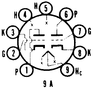
Tube Substitutions for:
9AU7
Medium Mu Duo Triode
| Type | Substitutes | Base Diagram |
|---|---|---|
| 9AU7 |  | |
| Web References | 9AU7 (Tung-Sol) @ Franks Electron Tubes 9AU7 @ RadioMuseum.org | |
| Type | Substitutes | Base Diagram |
|---|---|---|
| 9AU7 |  | |
| Web References | 9AU7 (Tung-Sol) @ Franks Electron Tubes 9AU7 @ RadioMuseum.org | |
| Bulb | T-61/2 |
| Base | Small Button 9-Pin |
| Basing | 9A |
| Mounting Position | Any |
| Heater Voltage Series/Parallel | 9.0/4.5 | Volts |
| Heater Current Series/Parallel | 225/450 | Ma |
| Heater Warm-up Time | 11 | Seconds |
| Max Heater-Cathode Voltage D.C. and Peak | 200 | Volts |
| Max Heater-Cathode Voltage D.C., Heater Positive | 100 | Volts |
| Grid to Plate Section 12 | 1.5 | 1.5 | ��f |
| Grid to Plate Section 22 | 1.5 | 1.5 | ��f |
| Input: (g to h + k) Section 1 | 1.8 | 1.6 | ��f |
| Input: (g to h + k) Section 2 | 1.8 | 1.6 | ��f |
| Output: (g to h + k) Section 1 | 2.0 | 0.40 | ��f |
| Output: (g to h + k) Section 2 | 2.0 | 0.32 | ��f |
| Plate Voltage | 300 | Volts |
| Plate Dissipation4 - Each Plate | 2.75 | Watts |
| Plate Dissipation4 - Both Plates | 5.5 | Watts |
| Average Cathode Current | 20 | Ma |
| Grid Circuit Resistance - Fixed Bias | 0.25 | Megohm |
| Grid Circuit Resistance - Cathode Bias | 1.0 | Megohm |
| Plate Voltage | 300 | Volts |
| Peak Positive Plate Voltage | 1200 | Volts |
| Plate Dissipation4 - Each Plate | 2.75 | Watts |
| Plate Dissipation4 - Both Plates | 5.5 | Watts |
| Peak Negative Grid Voltage | 250 | Volts |
| Average Cathode Current | 20 | Ma |
| Peak Cathode Current | 60 | Ma |
| Grid Circuit Resistance - Cathode Bias | 2.2 | Megohms |
| Plate Voltage | 300 | Volts |
| Plate Dissipation - Each Plate | 2.75 | Watts |
| Plate Dissipation - Both Plates | 5.5 | Watts |
| Peak Negative Grid Voltage | 400 | Volts |
| Average Cathode Current | 20 | Ma |
| Peak Cathode Current | 60 | Ma |
| Grid Circuit Resistance - Cathode Bias | 2.2 | Megohms |
| Plate Voltage | 300 | Volts |
| Plate Dissipation - Each Plate | 2.75 | Watts |
| Plate Dissipation - Both Plates | 5.5 | Watts |
| Peak Negative Grid Voltage | 600 | Volts |
| Average Cathode Current | 20 | Ma |
| Peak Cathode Current | 300 | Ma |
| Grid Circuit Resistance - Cathode Bias | 2.2 | Megohms |
| Plate Voltage | 100 | 250 | Volts |
| Grid Voltage | 0 | -8.5 | Volts |
| Plate Current | 11.8 | 10.5 | Ma |
| Plate Resistance (approx.) | 6500 | 7700 | Ohms |
| Transconductance | 3100 | 2200 | �mhos |
| Amplification Factor | 20 | 17 | X |
| Grid Voltage for Ib=10�a (approx.) | -24 | Volts |
| 1 | External shield No. 315 connected to cathode of section under test. |
||
| 2 | Section No. 1 connects to pins 6, 7 and 8. Section No. 2 connects to pins 1, 2 and 3. | ||
| 3 | For operation in a 525-line, 30 fram system, the duty cycle of the voltage pulse must not exceed 15% of one scanning cycle. | ||
| 4 | In stages operating with grid leak bias, an adequate cathode bias resistor or other suitable means is required to protect the tube in the absence of excitation. |
| Heater Voltage Series/Parallel | 12.6/6.3 | Volts | |
| Heater Current Series/Parallel | 150/300 | Ma |