Tube Substitutions for:
6SN7
Medium Mu Duo Triode
| Type | Substitutes | Base Diagram |
|---|---|---|
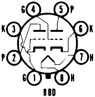
| 6SN7 | 6SN7W, 6SN7WGT, 6SN7WGTA, 5692 |  |
| Web References | 6SN7 (RFT) @ Franks Electron Tubes 6SN7 @ RadioMuseum.org | |
| Type | Substitutes | Base Diagram |
|---|---|---|
| 6SN7 | 6SN7W, 6SN7WGT, 6SN7WGTA, 5692 |  |
| Web References | 6SN7 (RFT) @ Franks Electron Tubes 6SN7 @ RadioMuseum.org | |
| Bulb | MT-8 |
| Base | Intermediate Shell Octal 8-Pin |
| Basing | 8BD |
| Mounting Position | Any |
| Heater Voltage | 6.3 | Volts |
| Heater Current | 600 | Ma |
| Section 12 | Section 2 | ||
| Grid to Plate | 240 | 3.8 | ��f |
| Input | 2.2 | 2.6 | ��f |
| Output | 0.7 | 0.7 | ��f |
| Plate Voltage, C D | 300 | Volts |
| Vertical Amp Peak Postive Voltage | 1200 | Volts |
| Plate Dissipation (each plate) | 3.5 | Watts |
| Plate Dissipation (both Plates) | 5.0 | Watts |
| Plate Voltage | 90 | 250 | Volts |
| Grid Voltage | 0 | -8.0 | Volts |
| Plate Current | 10 | 9.0 | Ma |
| Plate Resistance | 6700 | 7700 | Ohms |
| Transconductance | 3000 | 2600 | �mhos |
| Amplification Factor | 20 | 20 | X |
| Grid Voltage for Ib=1.3Ma | -12.5 | Volts | |
| Grid Voltage for Ib=10�a | -7.0 | -18 | Volts |
| 1 | All ratings, operating conditions and characteristics are for each section except where otherwise noted. |
| 2 | Section No. 1 connects to pins 4, 5 and 6, Section No. 2 connects to pins 1, 2 and 3. |
| 3 | For operation in a 525-line, 30 frame system, the duty cycle of the voltage pulse must not exceed 15% of one scanning cycle. |