Home  Resources  References  Tubes  Forums  Links  Support  Sale 

Tube Substitutions for:
6L6GC
Beam Power Amplifier
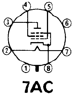
TypeSubstitutesBase Diagram
6L6GC6L6A, 6L6G, 6L6GA, 6L6GAY, 6L6GB, 6L6, 6L6GT, 6L6GX, 6L6Y, 5881, 7581, 7581A
Web References6L6GC (Mazda-Belvu) @ Franks Electron Tubes
6L6GC (RCA (HB3)) @ Franks Electron Tubes
6L6GC (Ei) @ Franks Electron Tubes
6L6GC (Tung-Sol) @ Franks Electron Tubes
6L6GC (RCA (RC30)) @ Franks Electron Tubes
6L6GC @ RadioMuseum.org
RCA Type 6L6GC
BEAM POWER TUBE


Bulb T-12
Base Intermediate Shell Octal
Basing 7S
Mounting Position Any


ELECTRICAL DATA


HEATER CHARACTERISTICS
Heater Voltage 6.3 Volts
Heater Current 900 Ma

DIRECT INTERELECTRODE CAPACITANCES
Grid No. 1 to Plate 0.6 ��f
Grid No. 1 to all but plate 10 ��f
Plate to all but Grid No. 1 6.5 ��f

MAXIMUM RATINGS (Design Maximum Values)
Plate Voltage 500 Volts
Grid No. 2 (Screen-Grid) Voltage 4501 Volts
Plate Dissipation 30 Watts
Grid No. 2 Input 5 Watts
Peak Heater Cathode Voltage Negative 200 Volts
Peak Heater Cathode Voltage Positive 200 Volts

TYPICAL OPERATION
Plate Voltage 350 Volts
Grid No. 2 Voltage 250 Volts
Grid No. 1 (Control-Grid) Voltage -18 Volts
Peak AF Grid No. 1 Voltage 18 Volts
Zero Signal Plate Current 54 Ma
Max Signal Plate Current 66 Ma
Zero Signal Grid No. 2 Current 2.5 Ma
Max Signal Grid No. 2 Current 7 Ma
Plate Resistance (Approx.) 33000 Ohms
Transconductance 5200 �mhos
Load Resistance 4200 ohms
Total Harmonic Distortion 15 Percent
Maximum Signal Power Output 10.8 Watts
Class A1 Amplifier (Triode Connection)2
Plate Voltage 250 Volts
Grid No. 1 Voltage -20 Volts
Peak AF Grid No. 1 Voltage 20 Volts
Zero-Signal Plate Current 40 Ma
Max-Signal Plate Current 44 Ma
Plate Resistance (Approx.) 1700 Ohms
Amplification Factor 8 X
Transconductance 4700 �mhos
Load Resistance 5000 ohms
Total Harmonic Distortion 5 Percent
Maximum Signal Power Output 1.4 Watts
Push-Pull Class A1 Amplifier
Plate Voltage 270 Volts
Grid No. 2 Voltage 270 Volts
Grid No. 1 Voltage -17.5 Volts
Peak AF Grid No. 1 to Grid No. 1 Voltage 35 Volts
Zero Signal Plate Current 134 Ma
Max Signal Plate Current 155 Ma
Zero Signal Grid No. 2 Current 11 Ma
Max Signal Grid No. 2 Current 17 Ma
Effective Load Resistance (Plate to Plate) 5000 Ohms
Total Harmonic Distortion 2 Percent
Maximum Signal Power Output 17.5 Watts
Push-Pull Class AB1 Amplifier
Plate Voltage 450 Volts
Grid No. 2 Voltage 400 Volts
Grid No. 1 Voltage -37 Volts
Peak AF Grid No. 1 to Grid No. 1 Voltage 70 Volts
Zero-Signal Plate Current 116 Ma
Maximum Signal Plate Current 210 Ma
Zero Signal Grid No. 2 Current 5.6 Ma
Maximum Signal Grid No. 2 Current 22 Ma
Effective Load Resistance (Plate to Plate) 5600 Ohms
Total Harmonic Distortion 1.8 Percent
Maximum Signal Power Output 55 Watts
Push-Pull Class AB2 Amplifier
Plate Voltage 360 Volts
Grid No. 2 Voltage 270 Volts
Grid No. 1 Voltage -22.5 Volts
Peak AF Grid No. 1 to Grid No. 1 Voltage 72 Volts
Zero Signal Plate Current 88 Ma
Max Signal Plate Current 205 Ma
Zero Signal Grid No. 2 Current 5 Ma
Max Signal Grid No. 2 Current 16 Ma
Effective Load Resistance (Plate to Plate) 3800 Ohms
Total Harmonic Distortion 2 Percent
Maximum Signal Power Output 47 Watts
Maximum Circuit Values
Grid No. 1 Circuit Resistance, Fixed Bias 0.1 Megohm
Grid NO. 1 Circuit Resistance, Cathode Bias 0.5 Megohm

NOTES:

1 In push-pull circuits where grid No. 2 of each tube is connected to a tap on the plate winding of the output transformer, this maximum rating is 500 Volts.
2 Grid No. 2 connected to plate.

APPLICATION

The 6L6GC is primarily used in the output stage of audio amplifying equipment, especially units designed to have ample reserve of power delivering ability. This type provides high power output, sensitivity, and high effeciency. Power output at all levels has low third- and higher-order harmonics.


© 1996-2021 Nostalgia Air