Type | Substitutes | Base Diagram |
---|---|---|
5W4G | 5W4, 5W4GT, 5W4GT/G, 5AR4, 5CG4, 5R4G, 5R4GTY, 5R4GYA, 5R4GYB, 5T4, 5V4G, 5V4GA, 5V4GY, 5Y3G, 5Y3GA, 5Y3GT, 5Y3GT/G, 5Z4, 5Z4G, 5Z4GT, 5Z4GT/G, 5Z4MG | |
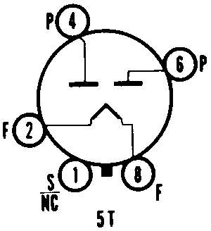
Web References | 5W4G (RCA (HB3)) @ Franks Electron Tubes 5W4G (Tung-Sol) @ Franks Electron Tubes 5W4G (Triad) @ Franks Electron Tubes 5W4G @ RadioMuseum.org |
Bulb | ST-12 |
Base | Small Wafer Octal |
Basing | 5T |
Mounting Position | Vertical preferred. |
Heater Voltage | 6.3 | Volts |
Heater Current | 1.5 | Amps |
Heater Positive with respect to Cathode | 200 | Volts (Max) |
Heater Negative with respect to Cathode | 200 | Volts |
Peak Inverse Voltage | 1400 | Volts |
Peak Plate Current Per Plate | 300 | Ma |
A-C Plate Voltage per Plate (RMS) | 350 | Volts |
Total Effective Plate Supply Impedence Per Plate1 | 25 | Ohms (Min) |
D-C Output Current | 100 | Ma |
Peak Inverse Voltage | 1400 | Volts |
Peak Plate Current Per Plate | 300 | Ma |
A-C Plate Voltage per Plate (RMS) | 500 | Volts |
Input-Choke Inductance | 6 | Henries (Min) |
D-C Output Current | 100 | Ma |
1 | When a filter-input condenser larger than 40�f is used, it may be necessary to use more plate-supply impedance than the minimum value shown to limit the peak plate current to the rated value. |