Tube Substitutions for:
12BY7
Pentode Video Amplifier
| Type | Substitutes | Base Diagram |
|---|---|---|
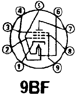
| 12BY7 | 12BY7A, 12BV7, 12DQ7, 7733, 8448 |  |
| Web References | 12BY7 @ RadioMuseum.org | |
| Type | Substitutes | Base Diagram |
|---|---|---|
| 12BY7 | 12BY7A, 12BV7, 12DQ7, 7733, 8448 |  |
| Web References | 12BY7 @ RadioMuseum.org | |
| Bulb | T-6� |
| Base | Small Button 9-Pin |
| Basing | 9BF |
| Mounting Position | Any |
| Heater Voltage | 12.6/6.3 | Volts |
| Heater Current | 300/600 | Ma |
| Heater Warm-up Time1 | 11 | Seconds |
| Maximum Heater-Cathode Voltage-Total DC and Peak | 200 | Volts |
| Maximum Heater-Cathode Voltage-DC, Heater + to Cathode | 100 | Volts |
| Grid to Plate | .063 | ��f |
| Input | 10.2 | ��f |
| Output | 3.5 | ��f |
| Plate Voltage | 300 | Volts |
| Plate Dissipation | 6.5 | Watts |
| Grid No. 2 Voltage | 180 | Volts |
| Grid No. 2 Dissipation | 1.1 | Watts |
| Grid No. 1 Voltage Negative | 50 | Volts |
| Grid No. 1 Voltage Positive | 0 | Volts |
| Grid No. 1 Resistance-Fixed Bias | 0.25 | Megohm |
| Grid No. 1 Resistance-Cathode Bias | 1.0 | Megohm |
| Plate Voltage | 250 | Volts |
| Grid No. 2 Voltage | 180 | Volts |
| Cathode Bias Resistor | 100 | Ohms |
| Plate Current | 26 | Ma |
| Grid No. 2 Current | 5.75 | Ma |
| Transconductance | 11000 | �mhos |
| Plate Resistance (approx.) | 93000 | Ohms |
| Grid No. 1 Voltage for Ib=20�a | -11.6 | Volts |
| Amplification Factor (Triode Connected) | 28.5 | X |
| Amplification Factor | 1035 | X |
| 1 | Applies to parallel connection only. |