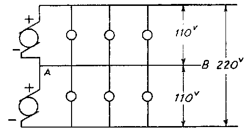
It was also mentioned that in a system of this sort the output of two generators is carried. Thus we can get 110 volts across either of the outer wires and the neutral wire. Across both outside wires we would get the output of both generators which would be 200 volts. See Fig. 13(b).
This is of importance to Radio-Tricians--they must understand this fact about three wire systems so that they will never connect a 110-volt receiver across the outer lines, as 220 volts applied to a 110-volt receiver would burn it out completely.
It is clear from what was said about the resistance of conductors why three-wire systems are used. Aside from the fact that 220 volts may be required for some types of apparatus, the three-wire system allows double the amount of current to be carried in the most economical manner. For large homes, where a great deal of current is drawn from the lines, if only a two-wire system were
Fig. 13(b)
used the wires would have to be extremely large to handle the heavy current drain. But by the use of three wires the same amount of current can be hauled using only one extra wire of ordinary size. The use of the neutral wire which is common to tube circuits results in a great saving of copper.
RADIO CIRCUITS
Now that we have laid the groundwork, having gotten a good knowledge of fundamental electrical circuits, we can go on to consider simple Radio circuits. Look at Fig. 14 which shows the complete transmitting and receiving network in outline form. The illustration is largely self-explanatory. Radio energy is sent out from the transmitting aerial and is picked up by the receiving aerial. Do we have one complete circuit? No, for the transmitter is not directly connected to the receiver. What we have