Home  Resources  References  Tubes  Forums  Links  Support  Sale  Search 

Back Next


    Now what is the total resistance of Fig. 10? There is no difficulty in solving this particular problem using equation (7).
G =  1 
R1
+  1 
R2
+  1 
R3
= 1
2
+ 1
5
+ 1
10

    By simple arithmetic—
1 divided by 2 = .5
1 divided by 5 = .2
1 divided by 10 = .1

G - .5 + .2 + .1 = .8 of a mho—Total Conductance.

Therefore R = 1/G = 1/.8 = 1.25 Ohms—Total Resistance.

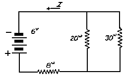
    Some radio circuits are combinations of series and parallel resistors like that shown in Fig. 11. Ohm's Law applies to every

Fig. 11—A series-parallel arrangement of resistance

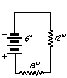
Fig. 12

part of this circuit. To find the total resistance, it is necessary first to reduce each parallel combination to its equivalent series resistance before combining it with the series resistance. For example, 20 ohms and 30 ohms in parallel are equal to 12 ohms. Therefore, 12 + 8 = 20, the total resistance of this series-parallel circuit. Series and parallel resistances will always be simple to understand especially if you are able to handle fractions and decimals, and have a clear understanding of the meaning of what reciprocal means. If you should find some of the methods used to obtain the total resistance of series and parallel resistance are not clear to you at first reading, a study of elementary arithmetic will clear matters up for you.

  Back 12 Next  


Content©1931, National Radio Institute
Webpage©1997, Nostalgia Air
Transcriber  Jennifer Ellis