Electrical Restoration of the RCA Radiola 18
| Bill Jeffrey | 8/23/97 |
 |
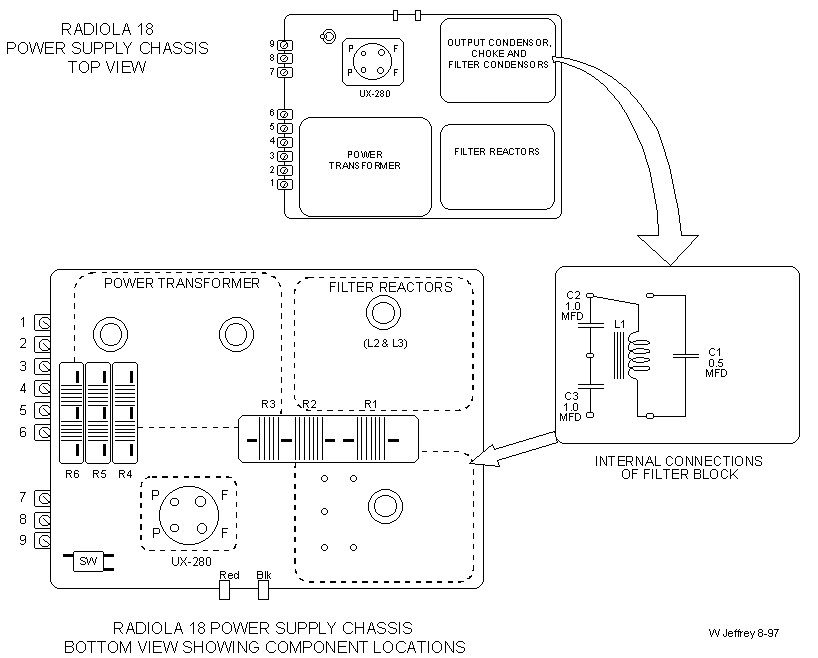
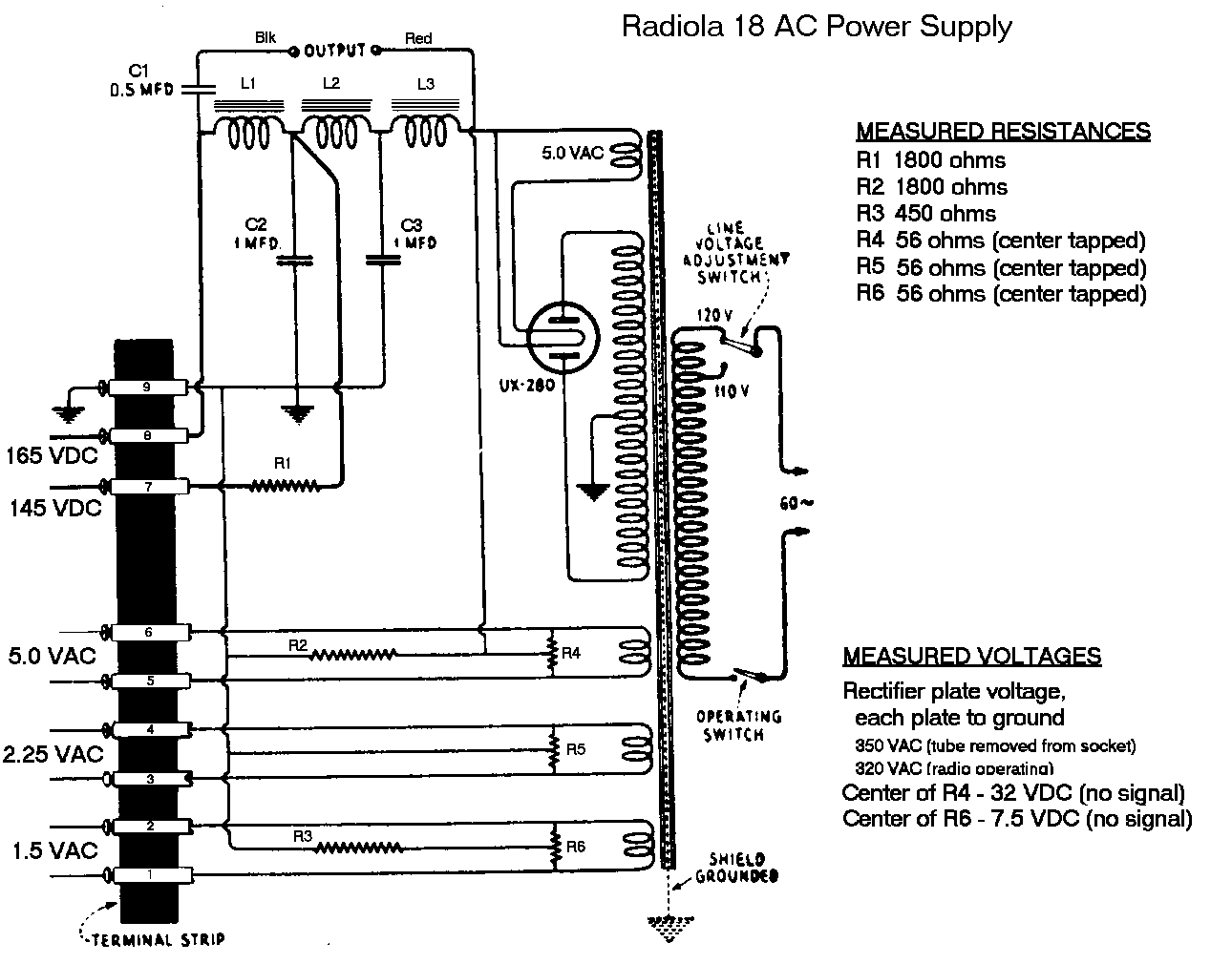
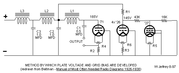
The Radiola 18 is a Tuned Radio Frequency (TRF) receiver typical of designs in the mid-1920's. It is a tabletop radio, housed in a substantial wooden case about 27 inches long, 9 inches high and 7 1/2 inches deep. The top lifts up on internal hinges to provide access to the electronics. Screw holes suggest that there should be a recessed back, but it is missing on my unit. Such a back would have been well-ventilated. This box arrangement was also common at the time, and is seen in many other radios. As the schematic shows, the receiver itself has 6 tubes. The AC model included a power supply on a separate chassis within the wooden case, with a 7th tube (a Type 80) as the rectifier. There was also a DC model of the Radiola 18. This was not an AC/DC set, as became common after World War II, nor was it a battery set. Instead, the DC model operated from 117 volts DC, a distribution standard which had been promoted loudly (and ultimately unsuccessfully) by Thomas Edison in the late 1800's. Even as late as the 1920's, several metropolitan areas in the US, including large sections of New York and Chicago, as well as smaller areas, received 117 VDC distribution. The circuitry in the AC and DC models was nearly identical, except for the lack of a power transformer and rectifier in the DC set, and some minor differences in the filament connections and grid bias arrangement. This article will concentrate on the AC model, but most comments apply to both. In the restoration of the Radiola 18, a number of interesting circuit details are encountered. An annotated schematic is shown below. The RF signal from the antenna/ground system is connected directly across a variable resistor (a potentiometer or "pot") right at the front of the signal chain. The desired amount of signal is picked off the wiper of the pot, and passed to the grid of the first RF amplifier. This provides the volume control for the set - if you want less volume, you simply decrease the amount of antenna signal which gets into the signal chain. It is also helpful, though not fully effective, in reducing overload of the RF amplifiers on strong local stations. This volume control is a big wirewound power rheostat, much larger than the function requires. It is unusual in that it has two resistance tracks. The main track totals about 3.3 kohms, and as in an ordinary rheostat, is in contact with the wiper over the full rotation of the control (about 3/4 of a turn). The pot is physically large in order to make room for a second resistance track which extends from the ground end to about 1/3 of the rotation. This second track, which totals only about 22 ohms, is mounted just inboard of the first, pressed against it, and in electrical contact with the main track all along its length. The overall effect is that, as the wiper comes up from the ground end, the resistance (and thus signal strength) increases quite slowly for the first third of the rotation, and then much more quickly thereafter. This gives a variable rate of control - slow at the low volume (high signal strength) end, and a faster adjustment at the top end. This is an approximation to the later "audio taper" pots. It is common for wirewound pots such as this one to have breaks in the resistance wire, and these are not repairable short of rewinding the resistance track. Further, the dual-track design means that an authentic replacement will probably be hard to find. My solution was to remove the entire shaft and wiper assembly from the center of the ceramic form, and mount a modern 2K carbon pot in its place, right on the ceramic form. This is not the purist's solution, but it is quick and easy, and looks reasonably good. Referring again to the schematic, it is seen that the first three tubes are RF amplifiers. They are Type 26 triodes (or one of the variants), operated with the grid at DC ground. Grid bias is developed by operating the cathode (filament) several volts above ground, as reviewed below in the section titled Method Of Developing Bias Voltages. Triodes do not develop a lot of gain because of their high grid-plate capacitance, so a good antenna system is required. Incidentally, newcomers to antique radio are occasionally concerned that these four-pin tubes don't seem to be keyed - that is, once a tube is removed, it is not clear how to orient it to put it back in its socket. Upon closer inspection, it can be seen that two of the pins are larger than the other two, and the holes in the socket match this size difference. These large pins are the filament connections, and they are heavy because the filaments draw nearly 2 amps of current for each tube. This explains why early battery sets had huge "A" batteries. After each RF amplifier, interstage tuning selects the station to be received. The three tuned circuits use air-core transformers wound on cardboard forms. They are mounted under the chassis, and oriented at right angles to each other to minimize coupling among them. When removing the Radiola chassis from the case, be especially careful of these coils. They are not well-protected, and the fine wire would be difficult to repair if broken. Tuning is done with a variable condenser across the secondary of each interstage transformer coil. All three sections of the tuning condenser are mounted on a common shaft and tuned with a single knob, a great operating convenience compared to the separate tuning controls of earlier radios. On Radiola 17's and 18's, this three gang tuning condenser is sometimes found to be bound up and difficult to turn, but restoration is quite straightforward. At some time in the past, a "gimmick" capacitor (a pair of wires twisted a few turns without removing the insulation) was added to my radio across the third section of the tuning cap. I have not removed it to see what happens, but it would appear that the third condenser section did not "track" the other two, and a small amount of additional capacitance was required. Since there are no trimmers on the tuning caps, this would have been a quick solution. Referring again to the schematic, it is seen that at the output (plate) of the second tube, the amplified signal is connected to the tuning for the third tube, as expected. However, there is also a connection to a "mystery component" which wraps back toward the input of the second tube. The component is a mystery on printed schematics, because the symbol does not reproduce well. It is also a mystery in the radio itself, because you can't see it. It is mounted on a small flat plate which is in turn riveted upside down to the bottom of the chassis. I have recently found a schematic of the AC set where the symbol is decipherable. It turns turns out to be a small compression condenser, so the symbol has been cleaned up on the schematic below. Although there are other possibilities, this path through the mystery component probably provides regeneration, a technique for increasing the gain of an amplifier. The signal at the input (grid) of the second tube is amplified and appears at the plate. Then a portion of that amplified signal is coupled back to the input of the tube, and amplified again. This is a somewhat fussy process, since if too much of the signal is fed back (or is fed back in the wrong phase), the amplifier will break into oscillation. On the other hand, if too little is fed back, the radio will lack sensitivity. The correct feedback is chosen by tweaking this mystery component, called a compensating condenser in the Radiola 18, according to the instructions on the schematic. The fourth tube, a Type 27, is the detector, which extracts the audio from the amplified RF signal. The circuit arrangement used here, called a grid-leak detector, is characterized by a relatively high grid bias (provided by the high value grid resistor) and a low plate voltage (provided by the voltage divider in the tube's B+ line). With this combination, the tube is biased in cutoff (no plate current), and conducts only on the positive peaks of the incoming RF signal. This is just what is needed for a detector. The detected audio is passed through an iron core interstage transformer to the fifth tube, another Type 26 triode, which is used as an audio preamplifier. Another interstage transformer brings it to the audio power amplifier, Type 71, and then out to the speaker. It should be noted that the Type 71 tube expects a speaker load on the order of 2-4 Kohms. In the original radio, this load was probably provided by a horn speaker, whose driver consisted of several hundred turns of fine wire. If a modern low-impedance speaker (typically 8 ohms) is to be used, a small output transformer will be needed. Any impedance ratio on the order of 2 or 4 Kohms (primary) to 8 ohms or so (secondary) will work fine. No DC current passes through this transformer, so DC voltage or DC current ratings are unimportant. The RCA schematic diagram for the Radiola 18 does not call out most of the component values. Without this information, getting a dead radio working again can be trickier than it should be. To ease this problem, measured component values are shown. It should be emphasized that the values shown were measured in a single working radio, so they are indicative, but may not reflect the "official" design values. Your radio may differ somewhat, and if an RCA schematic with parts values becomes available, it should be used in preference to these. A few measured voltages are also shown, with the same caveat. Your voltages may differ somewhat, especially in the area of the detector tube. The Radiola 18's AC power supply is located on a separate chassis, connected to the receiver via a 9-lug terminal strip. The design uses a full-wave rectifier (a Type 80 tube), and is fairly standard for the era. However, a couple of extra features are included which indicate a little higher quality than was common in these sets. These include the use of an electrostatic shield in the power transformer, to isolate the radio from high frequency disturbances on the power line, and the use of 3 sections of filter choke, rather than the more common 2-section filter. The result is a radio with very little hum in the output. The audio is surprisingly good. The power supply includes several hefty power resistors mounted under the chassis. The heat generated by these resistors was trapped under the chassis, and as a result, the cloth-over-rubber insulation on the wires will be quite brittle. Avoid moving the wires around if you can, and be gentle if you must move them. There are high voltages here, so if the insulation crumbles off any wires, you must replace it with either electrical tape or spaghetti sleeving. The movement involved in applying the tape or sleeving will surely crumble more insulation, so avoid even starting down this road if at all possible. The high under-chassis temperature also accelerated the corrosion of the wire-wound resistors, and it is common to find Radiolas with open resistors. Rewinding these resistors is possible but difficult. A 2-watt carbon resistor of the appropriate value, soldered onto the existing terminals, will suffice for most restorations. Resistance and voltage values measured in one working radio are also shown, with the same comment as noted above. Most of the power supply components are potted in steel cans mounted on the chassis, and it is not immediately clear which can contains any given component on the schematic. The sketch lays this out as an aid to troubleshooting. For those who are interested in circuitry details, the simplified bias voltage circuit is included below. This circuit is redrawn from Beitman's "Most Often Needed Radio Diagrams 1926-1938", and annotated with measured resistance and voltage values. For most applications, vacuum tubes want to run with the grid a few volts negative with respect to the cathode. One way to accomplish this is to run the cathode at ground, and apply a negative "C" voltage to the grid. The "C" voltage is provided by a separate battery, or a section of the power supply. Another way, and the one chosen for this radio, is to run the grids at ground potential, and the cathode a few volts above ground (which puts the grid voltage below the cathode voltage, as desired). For these tubes, there is no separate cathode - the cathode is the filament - so the split resistors, with the center tap tied to ground, raise the "cathode" above DC ground while also providing AC heater voltage. This article has concentrated on the electrical restoration of the Radiola 18, but the wooden case should not be ignored. It was rugged, well constructed, and unless substantial damage has been done, should clean up nicely. Tips on cabinet restoration can be found in many sources. The schematic diagram identifies the pilot lamp for the radio as a Mazda T-3 (6 volt, 0.15 amps). The common type 40 (screw base) or type 47 (bayonent base) lamp would serve as well. When the radio was new, a decorative metal hood was mounted on the bezel to shield the pilot lamp. On the original radio, this hood was only loosely attached, and it is commonly found to be missing on Radiolas. Fortunately, a replacement is available from Antique Electronics Supply in Tempe, Arizona, for a very modest price. This source does not have a web site (yet! they assure me), but will send a catalog if you call them at 602-820-5411. Finally, an excellent source of information, tips, and techniques for the restorer is "Antique Radio Restoration Guide" by David Johnson. The author covers not only the mechanics of electrical and cosmetic restoration, but also presents overviews of the theory behind common circuit functions, and the building and use of test equipment as well. Unfortunately, Fordham Radio, which the author often cites as a great source of parts and equipment, has gone out of business. Editors Note: These images look best printed, below they are scaled to fit the page. It is not recommended that you print from your browser. <% 'Windows95 'Win95 'WinNT 'Win32 'Win16 'MacPPC 'Mac68K 'WinCE 'UNIX Set bc = Server.CreateObject("MSWC.BrowserType") Browser = bc.Browser OpSys = bc.Platform Version = bc.Version Choice = Browser & ":" & OpSys SELECT CASE Choice CASE "IE:Win95", "IE:WinNT", "IE:Windows95" Instruction = "To Save the Image using " & Browser & " " & Version & " for " & OpSys & " right mouse click on image, select 'Save Picture As...' and save the file." CASE "IE:MacPPC", "IE:Mac68K" Instruction = "To Save the Image using " & Browser & " " & Version & " for " & OpSys & " click on image and hold when the menu appears, select 'Download Image to Disk' and save the file." CASE "Netscape:MacPPC", "Netscape:Mac68K" Instruction = "To Save the Image using " & Browser & " " & Version & " for " & OpSys & " click on image and hold when the menu appears, select 'Save this Image as' and save the file." CASE "Netscape:Win95", "Netscape:WinNT", "Netscape:OS2" Instruction = "To Save the Image using " & Browser & " " & Version & " for " & OpSys & " right mouse click on image, select 'Save Image As...' and save the file." CASE ELSE Instruction = "Most browsers will let you save the image." End Select %> <%= Instruction %> You may then open and print it using your favorite graphics/paint program. 


|
 |